1.Grinding accuracy:
1.1 Grinding accuracy: standard test piece
| No |
Items |
Machine tool acceptance |
| 1 |
Inner and outer circle runout |
0.005mm |
| 2 |
End face runout |
0.005mm |
| 3 |
Inner and outer raceway surface roughness |
Ra0.4μm |
| 4 |
End face surface roughness |
Ra0.63μm |
1.2 Machine tool geometric accuracy
1.2.1 Workpiece spindle rotation accuracy:
a. Radial runout of the spindle centering surface 0.003mm
b. Axial runout of the spindle 0.003mm
c. End face runout of the spindle shoulder support 0.003mm
1.2.2 Runout of the centering cone of the grinding wheel spindle: 0.003 mm
1.2.3 Positioning accuracy of X1, X2, Z1, Z2 axis 0.012mm
1.2.4 Repeated positioning accuracy of X1, X2, Z1, Z2 axis 0.005mm
1.2.5. Resolution of X1, X2, Z1, Z2 axis 0.001mm
2. Grinding plan:
The machine tool adopts multi-pole permanent magnetic chuck and is equipped with magnetic blocks for clamping bearing ring parts.
The machine tool can meet the high-precision grinding of surfaces such as V-shaped raceways, R-shaped raceways and end faces, and can also meet the grinding processing requirements of inner holes, outer circles and conical surfaces.
Machine tool grinding method: For surfaces such as raceways and V-shaped raceways, the machine tool adopts plunge grinding; for surfaces such as conical surfaces, cylindrical surfaces, and planes, the machine tool adopts reciprocating grinding.
The workbench can be started and adjusted manually, or it can be set in the automatic grinding program. The speed percentage adjustment can also be used in automatic grinding.
3. Technical performance, machine function description and technical parameters
3.1. Technical performance description
3.1.1. Basic requirements of machine tools
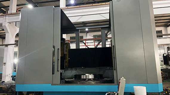
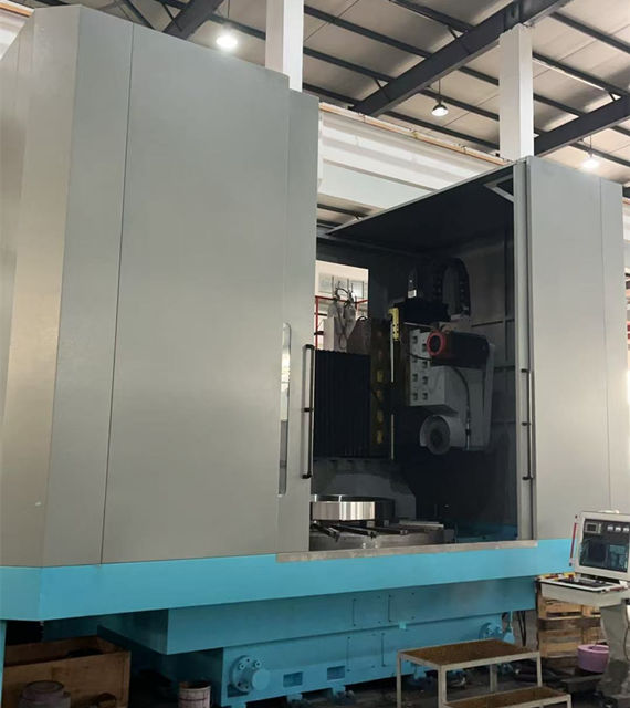
3.1.1.1. MS-2000 is a four-axis two-axis linkage vertical CNC grinding machine. It can grind multiple surfaces such as inner holes, outer circles, raceways, and end faces in one clamping. The machine tool adopts a modular structure. The overall layout is shown in the figure below. The workpiece spindle is fixed on the bed to drive the workpiece to rotate. Two axes (X1 and X2) are arranged in parallel on the crossbeam. The X1 axis is used for left slide grinding feed, and the X2 axis is used for right slide grinding reciprocating. The upper and lower reciprocating grinding frame axes (Z1 and Z2) are installed on the X1 and X2 axes respectively. A high-precision imported vertical grinding spindle is installed on the Z1 axis for precision grinding of internal and external raceways and other surfaces. A high-rigidity domestic vertical grinding head is installed on the Z2 axis for precision grinding of outer circles, inner circles, and end faces. The system can eliminate the positive and reverse clearance of each moving axis. The electric box is installed on the right side behind the bed, and the electric control box is fixed on the front right side of the bed, which is convenient for operation and adjustment.
3.1.2. The machine tool crossbeam and the upper and lower reciprocating grinding frame moving guide rails adopt roller type rolling guide rails produced by INA. The load bearing capacity, rigidity, precision and vibration resistance of this guide rail are superior to other guide rails. In order to ensure high load bearing rigidity, the crossbeam guide rail layout adopts a 90-degree intersecting installation surface layout.
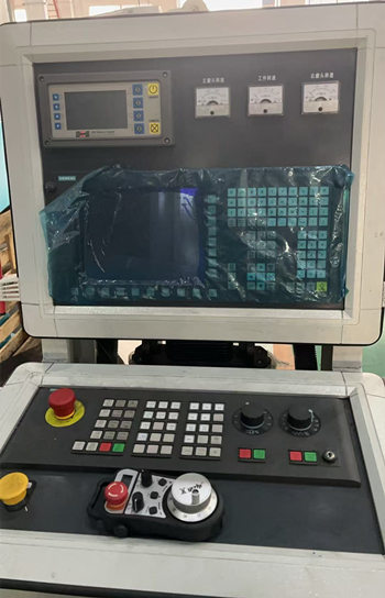
3.1.3. All servo axes have Siemens AC servo motors driving high-precision ball screws, and the control system adopts Siemens 828D CNC system.
3.1.4. The bed is a box-shaped casting structure with high rigidity and vibration resistance. There are large sloped water troughs around the top surface of the bed, and there is continuous coolant flushing to ensure that there is no accumulation of grinding chips on the bed surface.
3.1.5. The machine tool adopts a closed cover, which is safe and reliable, and can prevent coolant splashing and pollution. All guide rails, ball screws, and drive devices are also protected by fully enclosed covers to prevent water mist and oil mist from entering, which affects the life of the guide rails and drive devices.
3.1.6. In order to ensure the rotation accuracy and precision retention of the machine tool, the workpiece spindle adopts a high-precision full-static pressure spindle. The workpiece spindle is driven by a precision reduction device and a unloading belt, and the speed is variable-frequency stepless speed regulation by a frequency converter.
3.1.7. The machine tool adopts an electric permanent magnetic chuck worktable, the magnetic poles are radial, and the table has multiple T-slots for installing workpiece supports. According to the size of the workpiece to be processed, the magnetic force of the chuck can be adjusted, and the maximum magnetic force of the chuck is 15 kg/cm2. It also has an attenuation demagnetization device and demagnetization protection function, and has a magnetized and demagnetized display light.
3.1.8. The left vertical grinding head adopts a high-precision imported vertical grinding spindle for precision grinding of internal and external raceways and other surfaces. The right vertical grinding head adopts a vertically mounted high-rigidity mechanical grinding head for precision grinding of outer circles, inner circles, and end faces. The grinding head is driven by the spindle motor through a belt. Both the left and right grinding heads adopt variable-frequency stepless speed regulation by a frequency converter.
3.1.9. The upper and lower reciprocating grinding frame axes (Z1, Z2, X1, X2) are balanced by Taiwan hydraulic balancing devices to increase the life of motion actuators. The grinding frame can be self-locked in both power-on and power-off conditions to prevent the tool from falling during grinding and the grinding frame from sliding down under gravity after power failure.
3.2.Electrical system

3.2.1.The operating conditions of Party A's machine tool are: power supply 380V±10%, 50Hz±2%. The lighting voltage of the machine tool is AC220V.
3.2.2.The entire electrical system complies with the national standard GB/T5226.1-2016. Provide the brand of conventional electrical components.
3.2.3.The CNC system uses Siemens 828D CNC system.
3.2.4.The electrical system has a fault diagnosis function. When a fault occurs, the diagnosis content can be displayed on the display screen.
3.2.5.The electrical box is completely sealed, and the electrical box cooling air conditioner is installed. There is a lighting device in the electrical cabinet.
3.2.6.The grinding wheel speed and workpiece speed can be displayed in the control box.
3.2.7.The grinding spindles (Z1, Z2, X1, X2) of the machine tool adopt the closed-loop control method of Heidenhain grating ruler. It ensures that the two-axis linkage linear and circular interpolation have a high fixed-stroke grinding accuracy.
3.3. Cooling system
3.3.1. Equipped with a 160L/min high-flow cooling unit, the nozzle is adjustable, and the grinding cooling uses a high-lift pump to deliver water to ensure a good cooling effect.
3.3.2. The coolant is sufficient to prevent the processing accuracy from being affected by changes in the coolant temperature.
3.3.3. The coolant filter uses a magnetic and paper-tape precision filter device.
3.3.4. The cooling system is equipped with low-level and cooling blockage alarms.
3.4. Cleaning device
3.4.1. A cleaning pistol is installed for cleaning the fixture positioning surface, parts and machine tools.
3.5. Lubrication system
3.5.1. The machine tool guide rails and ball screws are centrally and automatically lubricated by Nanjing Beiqier's separate lubrication station.
3.5.2. The machine tool static pressure workpiece spindle is equipped with an independent hydraulic system, and is equipped with a filtering device and an air conditioning device.
3.6. Grinding wheel dresser
3.6.1 The left side of the machine tool is equipped with a set of single-point diamond pen dressers and a set of servo motor-driven arc single-point diamond pen dressers, of which the single-point dressers are used for the dressing of straight and V-shaped raceway (90 degrees) grinding wheels; the arc single-point diamond pen dressers are used for the dressing of the arc R of the grinding wheel.
3.6.2. The right side of the machine tool is equipped with a set of single-point diamond pen dressers for the dressing of the right vertical grinding wheel.
3.6.3. The machine tool has the functions of automatic grinding wheel dressing, automatic compensation, automatic grinding, etc.
3.7. Machine tool safety protection
3.7.1 The processing area is enclosed with a protective cover to prevent the leakage of chips, coolant, oil mist, etc. Ensure that there is no leakage of water, oil, and gas, and keep the working environment and surrounding work areas clean.
3.7.2. A transparent observation window is set on the operator side, and the transparent observation window is protected by explosion-proof plexiglass to prevent injuries after the grinding wheel is damaged.
3.7.3. Necessary lighting is set in the processing area for easy observation.
3.7.4. All moving parts such as ball screws and guide rails are equipped with fully enclosed protective devices to prevent chips, coolant, water mist, etc. from entering, which will affect the operating accuracy and life of the machine tool.
3.7.5. The working noise of the machine tool is ≤75dB.
3.7. Cutting tools
3.7.1. The grinding wheel is easy to install and disassemble and safe.
3.7.2. Two sets of left and right vertical grinding wheel chucks and one set of grinding wheel balance spindles are randomly provided. Parts drawings are attached.
3.8. The color of the machine tool is sky blue at the bottom and white paint at the top, or painted according to user requirements.
3.9. Main specifications of the machine tool
Grinding aperture range ¢600~¢2000mm
Maximum grinding outer diameter ¢2200mm
Maximum grinding depth 400mm
Maximum rotation diameter on the workpiece table ¢2200mm
Electric permanent magnetic chuck diameter ¢2200mm
Left crossbeam slide travel (X1 axis) 2000mm
Right crossbeam slide travel (X2 axis) 2000mm
Upper and lower slide travel (Z1, Z2 axis) 650mm
X1, X2 axis maximum moving speed 6m/min
Z1, Z2 axis maximum moving speed 6m/min
X1, X2 axis resolution 0.001mm
Z1, Z2 axis resolution 0.001mm
Left and right grinding frame rotation angle fine adjustment
Head spindle speed (frequency conversion speed regulation) 3~45r/min
Left vertical grinding head speed (frequency conversion speed regulation) 3000r/min
Left vertical grinding head power 30kw
Right vertical grinding head speed (frequency conversion speed regulation) 3000r/min
Right vertical grinding head power 18.5kw
Left vertical grinding head grinding wheel thickness range 30-150mm
Right vertical grinding head grinding wheel thickness range 30-100mm
Total machine power about 75kw
Maximum machine load 10000Kg
Machine tool dimensions 5600X4200X4700mm
Machine tool area 6500X6000X4700mm
Machine tool weight 52000kg
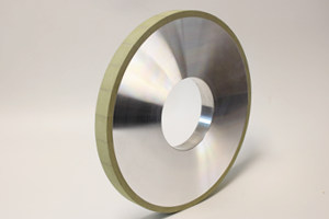
Applicable Precision Ceramic Grinding - Cylindrical Diamond Wheel

► Application: grinding various precision ceramic
► Bonded: resin bond & vitrified bond
► Correct choice of grain size and bonded
* Usually rough grinding uses D126, D91 (Resin bond &Vitrified bond)
* Semi-rough grinding uses D76, D64, D54, D46 (Resin bond & Vitrified bond)
* Semi-finish grinding uses D25, D20 (Resin bond &Vitrified bond)
* Finishing grinding uses D15 (Resin bond)
* Super finishing uses D7, D1 (Resin bond)


.jpg)


