1. Introduction: Application & Core Machining Challenges of Ceramic Matrix Composites (CMC)
Ceramic Matrix Composites (CMC) represent a cutting-edge class of ultra-high-performance advanced composite materials, structured with rigid ceramic matrices (SiC, Al₂O₃) reinforced by continuous high-strength fibers including silicon carbide fiber and carbon fiber. The mainstream industrial CMC material systems cover SiC/SiC (SiC fiber-reinforced silicon carbide), C/SiC (carbon fiber-reinforced silicon carbide), and C/C carbon-carbon composites.
Thanks to their outstanding comprehensive material properties—long-term service temperature exceeding 1300°C, one-third the density of superalloys, exceptional oxidation resistance, superior thermal shock resistance and lightweight structural rigidity—CMC materials have become irreplaceable core thermal structure materials for high-end aerospace and defense industries. Mass critical components manufactured from CMC include aero-engine combustor liners, turbine outer rings, guide vanes, aircraft carbon-ceramic brake discs, missile nose cones, and spacecraft thermal protection panels.
Despite remarkable high-temperature mechanical performance, CMC brings unprecedented severe obstacles to precision abrasive machining, which most aerospace manufacturers struggle to resolve stably in mass production. We summarize six core technical pain points restricting high-quality CMC grinding:
- Ultra-high hardness & strong anisotropy: SiC matrix hardness reaches HV 2500–3000, while reinforcing fibers exceed HV 2000. Oriented fiber arrangement creates drastic anisotropic grinding behavior, with inconsistent cutting resistance parallel and perpendicular to fiber orientation.
- Multi-phase heterogeneous structure triggering multi-type subsurface damage: CMC consists of three phases—ceramic matrix, reinforcing fiber, and weak PyC/BN interphase layer. Conventional grinding easily causes matrix cracking, fiber pull-out, interface debonding, and interlayer delamination, permanently weakening component mechanical performance and service safety.
- Extreme grinding force & high thermal load: Ultra-hard CMC raises specific grinding energy to 5–10 times that of metallic alloys, generating heavy grinding forces and concentrated heat. This accelerates rapid diamond grit wear and induces irreversible thermal damage on thin CMC workpieces.
- Extreme sensitivity to surface & subsurface defects: Aerospace-grade CMC components require a residual strength retention rate of no less than 90% post-grinding. Tiny microcracks or fractured fibers formed during machining act as fatigue failure initiation points under high-temperature cyclic operation.
- Rapid abrasive wheel wear & short service life: High abrasivity of CMC powder chips erodes diamond grains rapidly, resulting in frequent wheel dressing, long production downtime and elevated consumable costs.
- Thin-walled & complex shaped part deformation risk: Typical CMC parts such as brake discs and combustor liners feature thin wall thickness (2–5 mm). Grinding forces and clamping pressure easily trigger dimensional distortion and out-of-tolerance errors after finishing.
Core Guiding Principle for CMC Grinding Solutions
To tackle the inherent superhard, multi-phase, anisotropic characteristics of CMC materials, all custom grinding wheel design and process parameter optimization must adhere to four core targets:
minimize subsurface damage, control grinding force, suppress grinding temperature, and maintain workpiece geometric stability. This goal is achieved through high-toughness customized diamond abrasives, matched specialized bond systems, low-damage grinding parameter windows, and high-pressure intensive cooling circuits, enabling high-efficiency, low-defect machining covering full rough, semi-finish, and finish grinding workflows.
2. Custom Diamond Grinding Wheel Systematic Design for CMC Machining
MORESUPERHARD develops tailor-made CMC grinding wheels via five core design dimensions: abrasive grain type, bond system, diamond concentration, wheel hardness grade, and geometric wheel structure, fully adapted to diverse CMC material grades and machining stages.
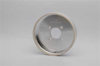
2.1 High-Toughness Sharp Synthetic Diamond Abrasive Selection
We exclusively recommend high-strength sharp-edged synthetic diamond over standard irregular diamond for all CMC grinding applications, with clear performance comparison as below:
| Comparison Item |
Conventional Standard Diamond |
Recommended High-Strength Sharp Diamond |
Design Rationale |
| Crystal Morphology |
Irregular fragmented blocks |
Equant intact crystals with multiple sharp cutting edges |
Sharp cutting edges reduce grinding resistance and localized heat generation |
| Compressive Strength |
≤20 kgf |
≥28 kgf |
Withstands heavy impact loads during CMC grinding to prevent premature grit fracture |
| Abrasion Resistance |
Average |
Excellent |
Resists severe abrasion from hard CMC chips and extends total wheel service life |
Grit Size Matching by Machining Stage
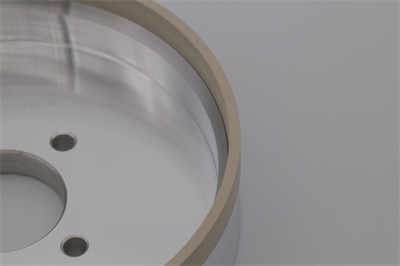
We provide tiered diamond grit specifications corresponding to different material removal volumes and surface integrity requirements:
| Machining Stage |
Recommended Diamond Grit |
Typical Workpiece Application |
Core Control Target |
| Rough Grinding / Stock Removal |
D91~D126 |
Brake disc thickness reduction, blank forming |
Fast material removal, leave 0.3–0.5 mm finishing allowance |
| Semi-Finish Grinding |
D46~D64 |
Combustor liner contour fine trimming |
Optimize form accuracy, limit subsurface damage depth |
| Finish / Final Grinding |
D20~D30 |
Final dimension sizing, sealing surface finishing |
Meet tight dimensional tolerances, subsurface damage ≤50 μm |
| Polishing & Surface Texturing |
D7~D15 |
Gas channel surfaces, pre-coating treatment |
Achieve Ra ≤0.4 μm, flatten exposed fiber tops |
Grit selection rule supplement: SiC/SiC composites feature harder SiC fibers than C/SiC, so select one grade finer grit for identical grinding stages to reduce fiber breakage.
2.2 Differentiated Bond System Matching by Machining Scenarios
Three mainstream bond types are deployed for segmented CMC production workflows, with targeted application scenarios:
| Bond Type |
Key Performance Features |
Suitable CMC Machining Scenarios |
Selection Logic |
| Resin Bond |
High elasticity, outstanding self-sharpening, low cutting force, anti-chip clogging |
Finish grinding, thin-wall components, complex curved contours |
Primary choice for low-damage CMC machining, minimizes fiber pull-out |
| Vitrified Ceramic Bond |
High rigidity, stable form retention, superior high-temperature resistance |
Rough grinding, mass planar surface grinding |
Ideal for high stock removal, maintains wheel geometry during long batch runs |
| Metal Bond |
Extreme structural strength, maximum wheel longevity |
Ultra-precision contour grinding, long uninterrupted production runs |
Delivers longest service life but requires dedicated diamond dressing rollers |
Critical bond structural design parameters:
- Resin bond wheels: 15%–25% high porosity for chip evacuation; high-temperature resin matrix with decomposition temperature ≥350℃; medium-soft hardness grade J–L to sustain consistent self-sharpening.
- Vitrified bond wheels: 20%–30% open porosity to boost coolant penetration and chip flushing; medium binder strength to balance rigidity and self-sharpening performance.
- Diamond concentration rule: Adopt medium-low concentration (50%–75%) for CMC grinding to cut single grit cutting depth and suppress matrix cracking and fiber debonding.
2.3 Diamond Concentration & Wheel Hardness Standard Parameters
| Parameter |
Recommended Range |
Engineering Design Basis |
| Diamond Concentration |
Rough grind: 75%–100% Finish grind: 50%–75% |
Lower concentration reduces single grit load, mitigating fiber pull-out and matrix crack propagation |
| Wheel Hardness Grade |
J–L (medium soft to medium hard) |
Slightly soft hardness ensures continuous self-sharpening, maintaining sharp cutting edges without excessive grinding force |
2.4 Custom Wheel Shape & Structural Optimization
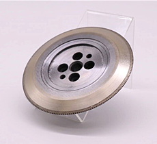
We manufacture a full lineup of standard and custom diamond wheel profiles for diversified CMC aerospace part geometries:
| Wheel Model Shape |
Main Application |
Core Optimized Design Details |
| 1A1 Straight Parallel Wheel |
Planar grinding of aircraft brake discs |
G1.0 ultra-precise dynamic balancing, optimized abrasive layer width |
| 6A2 Cup Wheel |
End-face grinding of combustor liners |
Uniform distributed radial cooling holes to deliver coolant directly to grinding arc zone |
| 11V9 Flaring Cup Wheel |
Contour grinding of turbine outer rings |
Custom contoured abrasive layer with form tolerance ≤0.02 mm |
| Fully Custom Special-Shaped Wheel |
Complex curved profiles, sealing grooves |
Wheel geometry produced per customer 3D CAD drawings |
Universal structural upgrades for all CMC grinding wheels:
- Lightweight high-strength aluminum alloy or carbon fiber wheel substrates to reduce spindle inertia and vibration.
- Strict dynamic balancing grade G1.0–G2.5 to eliminate vibration-induced fiber fracture and subsurface microcracks.
- Uniform radial cooling hole layout for full coolant coverage on complex grinding surfaces.
- Step reduced-diameter working layer for deep bore and internal profile grinding to avoid mechanical interference.
3. Optimized Complete CMC Grinding Process Parameter System
CMC grinding covers planar grinding, cylindrical grinding, and contour forming grinding. Below we release validated mass-production process parameters for two mainstream aerospace CMC workpieces: C/SiC aircraft brake discs (planar grinding) and thin-wall SiC/SiC combustor liners (external cylindrical & contour grinding).
3.1 Process Parameters for C/SiC Brake Disc Planar Grinding
Workpiece specification: Outer diameter φ300–500 mm, blank thickness 15–25 mm
Rough Grinding Stage (Single-side stock removal 0.4–0.6 mm)
| Parameter |
Recommended Value |
Setting Purpose |
| Wheel Surface Speed |
15–25 m/s |
Restrict linear velocity to avoid thermal degradation and fiber pull-out |
| Table Feed Speed |
5–15 m/min |
Balance material removal efficiency and subsurface damage control |
| Per-Stroke Grinding Depth |
0.01–0.03 mm |
Small depth-of-cut strategy to lower single grit cutting load |
| Cross Feed Rate |
1/3–1/2 of wheel width |
Ensure full surface coverage without missed grinding zones |
| Spark-Out Passes |
1–2 times |
Improve surface uniformity across entire disc plane |
Finish Grinding Stage (Final thickness tolerance ±0.03 mm)
| Parameter |
Recommended Value |
Setting Purpose |
| Wheel Surface Speed |
18–28 m/s |
Moderately elevated speed to refine surface roughness |
| Table Feed Speed |
4–10 m/min |
Reduced feed minimizes fiber fracture risk |
| Per-Stroke Grinding Depth |
0.003–0.010 mm |
Micro-cutting to lock dimensional accuracy and limit damage depth |
| Spark-Out Passes |
2–4 non-feed passes |
Eliminate elastic workpiece rebound and smooth exposed fiber tops |
3.2 SiC/SiC Combustor Liner Cylindrical & Contour Grinding Parameters
Workpiece feature: Thin wall 2–4 mm, high deformation sensitivity
| Parameter |
Recommended Value |
Setting Purpose |
| Wheel Surface Speed |
12–22 m/s |
Lower speed for harder SiC/SiC to suppress thermal damage |
| Workpiece Rotation Speed |
50–200 r/min |
Adjust based on liner outer diameter |
| Single-Stroke Grinding Depth |
0.005–0.015 mm |
Ultra-small cutting depth to prevent thin-wall distortion |
| Linear Feed Speed |
100–300 mm/min |
Slow steady feed for stable low-stress cutting |
| Spark-Out Passes |
2–3 times |
Eliminate surface waviness and reduce subsurface crack depth |
3.3 High-Pressure Intensive Cooling System Design (Critical Success Factor)
CMC grinding generates extreme concentrated heat and abrasive hard chip powder; high-flow high-pressure cooling is mandatory to eliminate thermal defects and secondary surface scratching:
| Cooling System Element |
Standard Configuration |
Technical Value |
| Coolant Fluid Type |
Fully synthetic grinding fluid or deionized water mixed with extreme pressure additives |
Low residue, outstanding heat transfer performance |
| Coolant Concentration |
2%–5% |
Prioritize cooling capacity over lubrication |
| Total Flow Rate |
60–120 L/min (scaled by wheel width) |
Mass flow flushes hot chips away instantly |
| Coolant Injection Pressure |
15–30 bar high-pressure jet |
Penetrates wheel abrasive gaps to reach grinding contact arc |
| Nozzle Layout |
Multi-ring distributed nozzles or spindle through-coolant |
Full coverage of every grinding contact zone |
| Filtration Precision |
≤5 μm absolute filter |
Remove sharp hard CMC chips to prevent secondary workpiece scratching |
| Coolant Temperature Control |
Constant 20±2℃ |
Stabilize thermal expansion for consistent dimensional accuracy |
Specialized cooling advice: For deep cavities and complex contours, adopt spindle center through-coolant to deliver coolant directly to the cutting point. Combine magnetic filters and paper tape filters to separate high-hardness CMC chip powder and protect coolant circulation cleanliness.
3.4 Standardized Wheel Dressing Regime
Rapid abrasive wear of CMC grinding wheels demands scientific dressing cycles to sustain consistent machining quality:
| Dressing Tool |
Operating Parameters |
Dressing Frequency |
Application Notes |
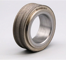
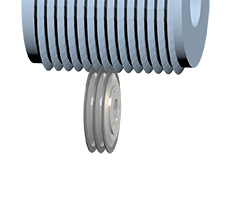
| Diamond Dressing Roller (Mass Production Preferred) |
Feed rate: 0.5–1 μm/rev, speed ratio +0.6~+0.8 |
Every 5–20 workpieces (depends on stock removal load) |
High dressing efficiency for continuous aerospace batch production |
| SiC Dressing Stick (Small-Batch Multi-Variety) |
Feed per stroke 0.005–0.01 mm, dressing depth 0.01–0.03 mm |
Every 1–3 workpieces |
Low-cost flexible option for small custom part orders |
Core dressing rules:
- Resin bond wheels require 2–3 non-feed spark-out passes post-dressing to remove abrasive edge burrs.
- Contour forming wheels must undergo contour inspection via profile measuring equipment after each dressing cycle.
- Trigger immediate dressing when spindle grinding force rises 15%–20%, surface roughness deteriorates, or fiber pull-out defects multiply.
3.5 Full-Process CMC Machining Quality Control Checklist
- Real-time grinding force monitoring: Set spindle load alarm thresholds to detect abnormal grit wear instantly.
- Thermal monitoring: Infrared thermal imaging to restrict grinding arc temperature below 200℃.
- Surface quality spot check: Ra ≤0.4 μm, no severe fiber pull-out or surface fracture.
- Subsurface damage inspection: SEM (Scanning Electron Microscope) or SAM (Scanning Acoustic Microscope) to detect hidden microcracks and interlayer delamination.
- Dimensional verification: CMM coordinate measuring machine for flatness, parallelism and thickness tolerance confirmation.
- Residual strength testing: First article strength validation to guarantee post-grinding residual strength ≥90%.
- Thin-wall deformation control: Vacuum suction or low-stress flexible clamping fixtures; micro-cutting low-force grinding strategy to minimize clamping and machining distortion.
4. Two Mature Mass-Production CMC Grinding Process Flows
Solution A: C/SiC Aircraft Brake Disc Planar Grinding (OD φ350 mm, thickness 20 mm → 19 mm finished)
| Process Step |
Custom Diamond Wheel Specification |
Key Process Parameters |
Quality Control Target |
| Rough Grinding |
Vitrified bond diamond wheel D107, 100% concentration, K hardness |
Vs=20 m/s, ap=0.02 mm, vw=10 m/min |
Fast thickness reduction, leave 0.3 mm finishing allowance |
| Semi-Finish Grinding |
Resin bond diamond wheel D46, 75% concentration, L hardness |
Vs=22 m/s, ap=0.008 mm, vw=8 m/min |
Refine surface texture, reserve 0.08 mm stock |
| Finish Grinding |
Resin bond diamond wheel D20, 50% concentration, M hardness |
Vs=25 m/s, ap=0.003 mm, vw=5 m/min, 3 spark-out passes |
Final thickness 19±0.03 mm, Ra≤0.4 μm, zero fiber pull-out |
Solution B: Thin-Wall SiC/SiC Combustor Liner External Cylindrical Grinding (Wall thickness 3 mm)
| Process Step |
Custom Diamond Wheel Specification |
Key Process Parameters |
Quality Control Target |
| Rough Grinding |
Resin bond diamond wheel D64, 75% concentration, K hardness |
Vs=18 m/s, ap=0.01 mm, feed 200 mm/min |
Reserve 0.15 mm allowance, suppress thin-wall deformation |
| Finish Grinding |
Resin bond diamond wheel D20, 50% concentration, M hardness |
Vs=22 m/s, ap=0.005 mm, feed 150 mm/min, 2 spark-out passes |
Full dimensional compliance, subsurface damage ≤50 μm, no interlayer delamination |
5. Conclusion
CMC ceramic matrix composites remain one of the most difficult-to-machine advanced materials for aerospace thermal components. Unoptimized generic diamond grinding wheels and uncalibrated process parameters inevitably lead to high reject rates, frequent wheel replacement, and compromised component service life. MORESUPERHARD delivers integrated one-stop CMC grinding solutions covering customized resin/ceramic/metal bond diamond wheels, matched high-pressure cooling configurations, standardized dressing schedules, and full-stage optimized machining parameters for C/SiC, SiC/SiC and C/C composite parts.
Our dedicated superabrasive engineering team supports global aerospace manufacturers with free sample wheel testing, on-site process parameter debugging, and custom wheel geometry design based on customer workpiece 3D drawings. If your production line faces persistent fiber pull-out, matrix cracking, short wheel lifespan, thin-wall distortion or low residual strength after CMC grinding, contact our international sales team today to acquire a tailored low-damage CMC machining package and cut your composite manufacturing costs significantly.