Modern precision manufacturing industries including mold making, aerospace component production, medical implant machining and micro-component fabrication are facing stricter demands for tighter dimensional tolerances, superior surface finish and stable high-speed spindle operation. Traditional clamping solutions such as ER collet chucks, side-lock holders and hydraulic tool holders frequently suffer from excessive radial runout, structural vibration, poor dynamic balance and limited cutting rigidity, which lead to poor workpiece surface quality, shortened cutting tool lifespan, unstable dimensional accuracy and low material removal efficiency.
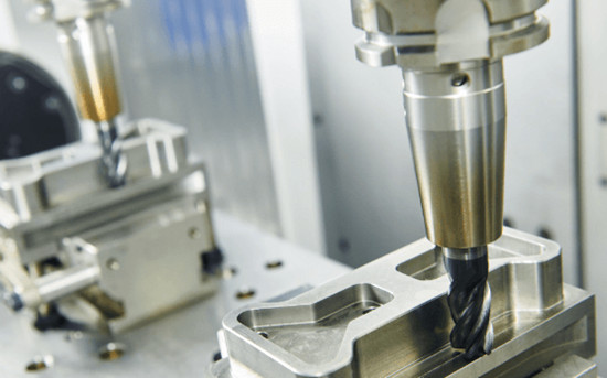
Shrink fit tool holders (also known as thermal shrink chucks) have emerged as the gold-standard clamping system to solve all these long-standing machining bottlenecks. This advanced tool holding system relies on the physical thermal expansion and contraction properties of high-strength alloy steel to deliver uniform, gap-free full-contact clamping force on cylindrical cutting tool shanks. Through standardized induction heating and controlled cooling workflows, shrink fit chucks achieve ultra-low runout, unmatched structural rigidity and excellent symmetrical balance, making them an indispensable accessory for high-precision, high-speed CNC machining centers worldwide.
1. Complete Working Principle of Shrink Fit Tool Holders
The entire tool mounting and dismounting cycle of shrink fit holders follows a strict thermal cycle, split into five standardized, repeatable steps with fully controllable temperature ranges:
Step 1: Targeted Induction Heating
Operators use a dedicated industrial induction shrink fit heater, the only approved heating device for this process. The front clamping section of the shrink fit tool holder is locally heated to a calibrated temperature window of 250°C to 400°C; the exact temperature threshold is adjusted based on the alloy grade, wall thickness and inner bore diameter of each shrink fit chuck. Open flame heating is strictly forbidden as uneven high-temperature exposure will permanently degrade the holder’s metallurgical structure, reduce clamping force and shorten service life drastically.
Step 2: Thermal Expansion of Inner Clamping Bore
As the front end absorbs controlled heat, the holder’s precision inner bore expands uniformly in all radial directions, creating a slight dimensional clearance that allows smooth insertion of the matching cylindrical tool shank without scratching the bore surface.
Step 3: Precision Tool Insertion
While the bore remains in expanded thermal state, the cutting tool shank is rapidly inserted into the holder until it reaches the pre-set depth stop position. Operators must ensure the tool shank is fully seated to avoid uneven clamping after cooling.
Step 4: Controlled Cooling & Contraction
Heating power is cut off immediately after tool positioning. Two safe cooling methods are permitted: natural ambient air cooling, or auxiliary low-pressure compressed air cooling to accelerate the cycle without thermal shock. Rapid water quenching is prohibited entirely, as uneven fast cooling will generate internal metal stress, deform the precision bore and destroy long-term clamping accuracy.
Step 5: Uniform Radial Clamping Force Formation
As the alloy steel cools back to room temperature, the holder bore shrinks tightly around the tool shank. The total clamping force originates purely from the powerful radial shrinkage stress of the metal alloy, delivering full-surface, zero-clearance wrapping contact along the entire length of the tool shank. This eliminates point contact, backlash and loose clamping that plague conventional collet holders.
2. 8 Core Competitive Advantages of Shrink Fit Tool Holders
Compared with ER chucks, hydraulic holders and side lock tool holders, shrink fit thermal chucks possess eight irreplaceable technical strengths tailored for high-end precision CNC production:
2.1 Ultra-High Clamping Precision with ≤3μm Radial Runout
The symmetrical full-contact shrink clamping mechanism eliminates eccentric offset caused by collet gaps or screw tightening imbalance. Certified radial runout at the tool tip is consistently controlled below 3μm, far exceeding the accuracy limits of standard clamping tools. This ultra-low runout directly stabilizes workpiece dimensional tolerance and eliminates periodic tool chatter marks, delivering mirror-grade surface finish for precision parts.
2.2 Superior Structural Rigidity & Vibration Suppression
Shrink fit holders feature a monolithic metal clamping structure with zero movable components, adjustment screws or segmented collets. The seamless metal-to-metal contact creates rigid force transmission during heavy cutting or high-speed milling. Vibration amplitude is drastically reduced even when machining tough hard materials such as hardened steel, titanium alloy and high-temperature superalloys, extending cutting tool service life by 20%–40%.
2.3 Excellent Inherent Dynamic Balance for High-Speed Spindles
The fully symmetrical cylindrical front profile has no protruding balance screws, offset clamping structures or uneven mass distribution points. As-manufactured shrink fit chucks achieve high-grade dynamic balance without secondary balancing treatment, perfectly matching high-RPM spindles operating at 15,000–40,000 RPM for micro-machining and high-speed mold finishing.
2.4 Exceptional Concentricity for Micro-Diameter Tools
Uniformly distributed radial shrinkage force centers the tool shank perfectly on the spindle rotation axis. This perfect concentricity is critical for micro machining with tiny diameter end mills (0.1mm–3mm), preventing tool breakage and ensuring consistent micro-feature dimensional accuracy on medical and semiconductor components.
2.5 Support for Extended Tool Overhang Length
The outstanding rigidity of shrink fit chucks resists bending deflection even with long tool extension lengths. Machinists can use longer tool overhangs to reach deep cavities, complex undercuts and multi-angle features on 5-axis workpieces without sacrificing precision, expanding the processing range of complex molds and aerospace structural parts.
2.6 Improved Machining Efficiency & Higher Material Removal Rate
Thanks to high rigidity and stable clamping accuracy, CNC operators can adopt more aggressive cutting parameters including higher spindle speeds, larger feed rates and deeper cutting depths. The enhanced metal removal rate shortens single-piece machining cycle time and boosts overall workshop throughput without raising reject rates.
2.7 Optimized Front Geometry for Unobstructed Chip Evacuation
Shrink fit holders feature a slim, streamlined front taper with no protruding screw heads, collet flanges or clamping accessories. This compact design eliminates chip accumulation and mechanical interference around the cutting zone, ideal for deep cavity milling and continuous mass production with heavy chip generation.
2.8 Broad Cross-Platform Compatibility for Global CNC Equipment
Our shrink fit tool holders support all mainstream international spindle connection standards: BT, HSK-A/HSK-E, CAT, SK and custom machine-specific tapers. They are universally compatible with all standard straight cylindrical shank cutting tools including end mills, drills, reamers and micro milling cutters, requiring no extra adapters for most global CNC machining centers.
3. Main Industrial Application Scenarios of Shrink Fit Chucks
Shrink fit thermal clamping holders are widely deployed across high-value precision manufacturing sectors with strict machining requirements:
- High-Speed Mold Manufacturing: Plastic injection molds, die-cast molds, stamping molds requiring ultra-smooth cavity surfaces and long tool overhang for deep mold cores.
- Aerospace & Aviation Precision Machining: Titanium alloy structural parts, superalloy turbine components, lightweight aircraft frame parts, where high rigidity and low vibration reduce tool breakage during hard material cutting.
- Medical Implant Machining: Titanium bone screws, joint prosthetics, dental implants and micro surgical parts that demand sub-micron dimensional accuracy and flawless surface finish.
- Hardened Steel & Difficult-to-Machine Material Processing: Pre-hardened mold steel, Inconel superalloys, titanium alloys, where vibration and runout will severely damage workpiece surface integrity.
- Micro Precision Machining: Small-diameter micro tools for semiconductor fixtures, tiny optical components and miniature precision mechanical parts, relying on the ≤3μm runout performance.
- 5-Axis Simultaneous Machining: Complex curved aerospace components, multi-angle mold inserts, where long tool overhang and balanced high-speed rotation are mandatory.
4. Critical Safe Operation Guidelines for Shrink Fit Tool Holders
To preserve holder precision, extend service life and avoid safety hazards during daily mass production, five core operation rules must be strictly followed by all workshop operators:
4.1 Only Use Professional Induction Heating Equipment
Manual open flame heating, gas torches or irregular heating tools are completely prohibited. Operators must use dedicated shrink fit induction heaters with precise temperature control modules. Excessive heating above 400°C will soften the alloy steel, degrade internal material properties and permanently reduce clamping force and runout accuracy.
4.2 Adopt Gradual, Shock-Free Cooling Protocols
Natural air cooling is the primary recommended method after heating. For faster cycle times, low-pressure dry compressed air cooling is acceptable. Direct water, coolant or liquid quenching is forbidden, as rapid uneven cooling creates internal thermal stress, bore deformation and irreversible loss of concentricity.
4.3 Match Precision Undamaged Tool Shanks
Tools fitted into shrink fit holders must feature high-tolerance ground cylindrical shanks with zero scratches, dents, deformation or surface corrosion. Mismatched shank diameters or damaged surfaces will create uneven clamping gaps, increase radial runout and cause premature tool loosening during high-speed rotation.
4.4 Maintain Absolute Cleanliness of Clamping Surfaces
Before every tool mounting cycle, thoroughly wipe the holder’s inner bore and tool shank to remove cutting oil, metal chips, dust and oxidation residue. Oil or debris trapped between the shank and bore creates slippery gaps that weaken clamping force and induce tool slip during heavy cutting.
4.5 Implement Periodic Regular Inspection Schedules
After repeated heating-cooling cycles (typically 50–100 tool changes), inspect each shrink fit holder for clamping force attenuation, bore dimensional deformation and radial runout deviation. Replace worn holders immediately once precision exceeds the allowable tolerance to avoid mass defective workpieces.
5. Conclusion
For CNC manufacturers struggling with excessive tool runout, poor surface finish, frequent tool breakage, unstable high-speed performance and limited deep cavity machining capability, shrink fit tool holders deliver a reliable, long-life high-rigidity clamping solution unmatched by traditional collet and hydraulic chucks. With consistent ≤3μm radial runout, symmetrical dynamic balance, broad spindle interface compatibility and outstanding performance on hard alloys, micro tools and 5-axis complex workpieces, thermal shrink fit chucks have become a core investment for mold, aerospace, medical and precision component factories worldwide.
Our factory supplies a full range of custom shrink fit tool holders covering BT, HSK, CAT spindle tapers, matched professional induction heating equipment and complete technical operation training for global clients. If you are seeking a stable high-precision clamping system to upgrade your CNC machining output and part quality, contact our international sales team for free product samples and customized technical solutions tailored to your machining center models and workpiece materials.