NEWS
14
Sep

Optical Milling & Grinding Process: Principles, Wheel Selection & Defects

Share:

What Is Milling and Grinding in Optical Fabrication?


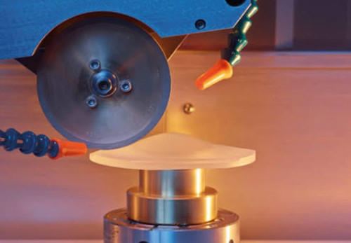
In optical fabrication, milling and grinding (often written as "mill-grind") is the rough machining process that uses a high-speed grinding wheel to rapidly cut optical blank material down to a shape and size close to the final lens specifications. It is the first precision step in the optical manufacturing chain—before polishing, edging, and coating. A well-executed milling process removes material quickly while leaving a controlled, uniform surface that makes subsequent polishing faster, cheaper, and more predictable. For lens manufacturers producing spherical and aspheric optics, understanding the milling process is essential to achieving high yields, tight tolerances, and consistent surface quality.

Core Components of a Spherical Milling and Grinding Machine


                            Milling in Optical Fabrication


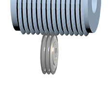
A typical spherical milling and grinding machine is engineered around one core objective: precisely controlling the relative motion trajectory between the grinding wheel and the workpiece to generate a spherical surface with the target curvature. To achieve this, the machine integrates several critical subsystems:
  • Grinding spindle: Delivers high rotational speed and rigidity to drive the wheel without vibration.
  • Workpiece spindle: Rotates and positions the optical blank relative to the wheel.
  • Cross-feed and swing mechanisms: Generate the spherical path by coordinating wheel and workpiece motion.
  • Coolant system: Supplies grinding fluid to the contact zone to control temperature and flush debris.
  • CNC control (for aspheric machines): Executes programmed tool paths for non-spherical geometries.
The geometric relationship between wheel radius, swing arm, and workpiece position determines the resulting sphere radius. Any deviation in alignment, spindle runout, or rigidity directly transfers into surface form error and roughness—which is why machine condition and wheel selection are equally important.

Typical Milling and Grinding Process Steps


                           Milling in Optical Fabrication


A standard optical milling sequence follows these stages:
  1. Blank preparation: Inspect the optical blank for size, material grade, and edge condition.
  2. Wheel selection: Choose the grinding wheel grit and bond based on material, part diameter, and target removal rate (see selection guide below).
  3. Machine setup: Mount the blank, align the wheel, and set spindle speed, feed rate, depth of cut, and coolant flow.
  4. Rough milling: Rapidly remove the bulk of excess material to approach final dimensions, typically with a coarser-grit wheel.
  5. Fine milling: Refine the surface with a finer-grit wheel to reduce roughness and improve form accuracy before polishing.
  6. Inspection: Measure surface roughness (Ra), curvature, and thickness to confirm the part is ready for polishing.
Throughout the process, coolant quality, spindle condition, and depth of cut must be controlled—these are the same factors that dominate defect generation, as discussed below.

Aspheric Milling: CNC Machines, Cup, Disc and Small-Head Grinding


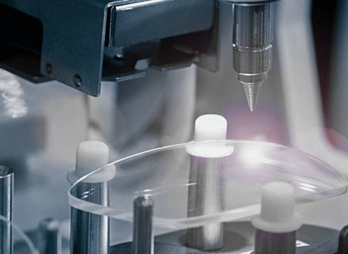
Aspheric lenses cannot be generated by the simple swing-arm geometry used for spheres. Instead, aspheric milling and grinding are typically performed on CNC milling/grinding machines, which follow a programmed tool path to produce the required rotationally symmetric or freeform profile. Three tool configurations dominate aspheric milling:
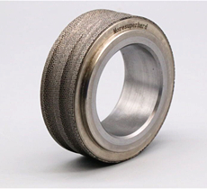
  1. Cup-shaped grinding wheels: Provide a stable, well-supported cutting edge for generating steep and varied profiles.
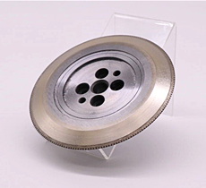
  2. Disc-shaped grinding wheels: Offer a large contact area and are efficient for shallower aspheric curves.
  3. Small grinding heads (ball-nose or pencil-edge): Allow localized material removal for tight radii, steep slopes, and corrective milling.
CNC machines with these tool options enable lens manufacturers to mill complex geometries in a single setup, reducing cycle time and improving repeatability compared to multi-step conventional processes.

Understanding Lens Abrasion Value and Its Role in Wheel Selection


The abrasion value of a lens material—a measure of how easily it is ground—is one of the most important parameters in optical milling. A lower abrasion value indicates a hard, wear-resistant lens; a higher value indicates a lens that is more brittle and easier to process. Practical guidance based on abrasion value:
  • Abrasion values 60–100: Relatively difficult to process. The larger the outer diameter, the harder the lens is to grind.
  • Abrasion values 110–160: Relatively easy to process—the sweet spot for efficient milling.
  • Abrasion values above 200: Difficult to process because the material is too soft and prone to surface scratches.
Understanding where your material falls on this scale helps you select the correct wheel grit, bond, and cutting parameters—avoiding both excessive wheel wear and surface damage.

Grinding Wheel Selection Guide by Part Diameter and Material


Wheel grit selection follows a straightforward logic based on the part's outer diameter (OD) and the material's hardness/heavy-metal content:
For parts with an OD smaller than Φ50 mm:
  • Soft material or high heavy-metal content: use a domestically produced 200#–300# grinding wheel.
  • Hard material, low or no heavy-metal content: use a Japanese-made 170#–270# grinding wheel.
For parts with an OD of Φ50 mm or larger:
  • Soft material or high heavy-metal content: use a domestically produced wheel of 200# or finer.
  • Hard material, low or no heavy-metal content: use a Japanese-made wheel of 170# or finer.
The logic: softer, heavier materials need finer grits to control surface quality, while harder, cleaner materials can use coarser Japanese wheels for better removal efficiency. Always verify with trial runs, as batch-to-batch material variation is common in optical glass and crystals.

Common Milling Defects and How to Fix Them


Poor surface roughness is the most common defect reported in optical milling. Its root causes and corrections are:

Defect: Poor Surface Roughness Corrective Action
1. Grinding wheel grit is too coarse Switch to a finer-grit wheel; re-check the selection guide above
2. Excessive machine tool vibration Inspect machine foundations, balance the wheel, tighten fixtures
3. Poor coolant quality or insufficient flow Replace coolant, increase flow rate, check nozzle aiming
4. Excessive depth of cut (feed rate) Reduce depth of cut; use multiple lighter passes
5. Loose grinding wheel spindle Tighten spindle; check taper fit and clamping
6. Worn or unlubricated spindle bearings Replace or lubricate bearings; verify spindle runout
7. Insufficient spark-out time Increase spark-out passes to let the surface stabilize

Best Practices for Consistent Optical Milling

 
  • Document wheel specs (grit, bond, brand) and cutting parameters per material and OD to build a repeatable process baseline.
  • Check spindle runout weekly and re-balance wheels after any dressing or re-mounting.
  • Keep coolant filtered and at a consistent concentration and temperature to stabilize results.
  • Use spark-out passes (zero-feed dwell) at the end of each cycle to reduce roughness and form drift.
  • Inspect wheels for glazing or loading between batches; dress with a diamond tool before defects appear.
  • Validate new wheel batches on sample parts before committing to production runs.

Why Choose Our Grinding Wheels for Optical Milling


We supply high-performance diamond and CBN grinding wheels engineered specifically for optical fabrication—including cup wheels, disc wheels, and small grinding heads for spherical and aspheric milling. Our wheels are manufactured with precisely controlled grit size, concentration, and bond formulation, delivering consistent material removal, low surface roughness, and long service life across optical glass, crystals, and ceramics. We offer full customization of diameter, grit, and profile to match your CNC milling machines and workpiece materials, plus application engineering support for parameter optimization and defect troubleshooting. Contact us today for a customized optical grinding wheel solution and technical consultation.

Conclusion


The optical milling and grinding process is the foundation of efficient, high-quality lens manufacturing. By understanding the machine principles behind spherical and aspheric generation, applying the abrasion-value framework, and following a disciplined wheel-selection guide based on part diameter and material, manufacturers can remove material fast while keeping surface quality under control. Equally important is defect prevention: most roughness problems trace back to a handful of controllable factors—grit size, vibration, coolant, depth of cut, spindle condition, and spark-out time. With the right wheel and disciplined process control, optical milling becomes a reliable, repeatable gateway to faster polishing, higher yields, and lower manufacturing cost.

Frequently Asked Questions


Q: What is the difference between milling and polishing in optical fabrication?
A: Milling (mill-grind) is the rough machining step that rapidly cuts the optical blank to near-final shape using a high-speed grinding wheel. Polishing comes after and uses fine abrasives on a lap to remove remaining roughness and produce an optical-quality surface. Good milling reduces polishing time significantly.
Q: What grinding wheel grit should I use for optical milling?
A: Grit depends on part OD and material. Under Φ50 mm: soft/high heavy-metal materials use 200#–300# domestic wheels; hard/low heavy-metal materials use 170#–270# Japanese wheels. For Φ50 mm and larger: 200# or finer (soft) and 170# or finer (hard). Always validate with trial runs.
Q: What does the abrasion value of a lens mean?
A: Abrasion value measures how easily a lens material is ground. Values 60–100 are relatively difficult to process; 110–160 are relatively easy; above 200 the material is too soft and prone to scratches. It is a key input for wheel grit and parameter selection.
Q: Why is my milled lens surface roughness too poor?
A: Common causes: wheel grit too coarse, machine vibration, poor coolant quality or flow, excessive depth of cut, loose spindle, worn or unlubricated spindle bearings, and insufficient spark-out time. Work through these seven factors in order to isolate the cause.
Q: How is an aspheric lens milled?
A: Aspheric lenses are milled on CNC machines using cup-shaped wheels, disc-shaped wheels, or small grinding heads. The CNC program drives the tool along a precise path to generate the aspheric profile in a single setup, enabling complex geometries with good repeatability.
Q: How do I choose between cup, disc, and small-head grinding wheels?
A: Cup wheels offer a stable edge for steep and varied profiles; disc wheels provide large contact area for shallower curves; small grinding heads allow localized removal for tight radii and steep slopes. Choose based on your lens profile and required material removal pattern.
 
FOLLOW US
This Blog keeps our valued customers informed of important Radiac News and Events, and in the industries we serve.
Copyright © 2003-2023 More SuperHard Products Co., Ltd
Home
Whatsapp
E-mail
Inquiry