NEWS
13
Nov

MSH-12S High-Precision Centerless Grinding Machine

Share:

What Through-Feed Centerless Grinding Actually Buys You


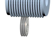
Centerless grinding removes the workpiece centre from the accuracy equation. The part is supported by a grinding wheel, a regulating wheel and a work rest blade, so long slender shafts—the parts that deflect and taper on a conventional cylindrical grinder—can be ground straight and round without fixtures. In through-feed mode the part travels axially between the wheels, driven by the regulating wheel's tilt, which makes the process continuous: load at one end, finished part out the other. For high-volume production of pins, needles, small shafts and bushings, that combination of accuracy and throughput is hard to match with any other process.
The limitation is equally clear: through-feed centerless grinding is best for straight, cylindrical features within a defined diameter and length band. The MSH-12S is designed around a 0.5 to 40 mm diameter range, which places it squarely in the small-precision-part market—fuel injector components, hydraulic pins, medical wire, spindle shafts, and similar work.


Five Design Decisions That Determine Accuracy


The specification sheet lists components. What matters is why each one is there.

1. The base is cast, stress-relieved, and aged—not welded.


The body and major structural components are cast in one piece from Meehanite FC30 high-grade cast iron, then given artificial normalising heat treatment followed by more than six months of natural aging. That sequence exists to release residual stress before machining, because a base that moves after machining will show up as taper and roundness error that no amount of parameter tuning can fix.

2. Major components are machined in a single setup.


Dimensional accuracy in the micron range depends on machining the interacting surfaces in one fixturing, not by re-datuming between operations. The specification calls for machining on high-end machine tools with the stated micron-level dimensional accuracy, which is the foundation the rest of the machine is built on.

3. The spindle is alloy steel, hardened, and cryogenically treated.


The spindle is SNCM-21H alloy steel, quenched and tempered, carburised, then computer-controlled cryogenic treated to a specified surface hardness above HRC 62, with an effective hardened depth beyond 1.5 mm on one side. Hardness at the surface resists wear; hardened depth resists deflection under load. Both matter, because a spindle that flexes microns under grinding force produces a part that is out of round.

4. The regulating wheel is servo-driven and directly belted.


The regulating wheel spindle is driven by a servo motor with numerical speed control across 0 to 320 rpm, designed to hold consistent linear speed as the regulating wheel diameter wears—which keeps workpiece feed rate stable between dressings. The motor is mounted on the regulating wheel housing and drives the spindle through a synchronous belt, so motor and wheel tilt together with the pulleys staying parallel. Compared with the multi-link chain drives of older centerless grinders, this reduces inertia loss and chain-angle effects, and removes the recurring maintenance of chains and tension springs.

5. Spindle oil is filtered twice and pressure-monitored.


The spindle runs on an automatic circulating lubrication system with No. 10 high-grade spindle oil, sharing one pump with the hydraulic dressing device and using an external tank for easy cleaning. Oil passes dual-circuit filtration with a pressure controller—the practical reason hydrodynamic spindles last: clean oil at stable pressure.


Technical Specifications at a Glance

 
Parameter MSH-12S
Workpiece diameter range 0.5–40 mm
Grinding wheel size (OD × width × bore) Ø305 × 150 × Ø120 mm
Regulating wheel size (OD × width × bore) Ø205 × 150 × Ø90 mm
Grinding wheel speed 1,950 rpm
Regulating wheel speed (variable) 0–320 rpm
Grinding wheel motor 5.5 kW
Regulating wheel motor (servo) 2.0 kW
Typical stock removal, rough / finish 0.03–0.06 mm / 0.005–0.02 mm


Accuracy: What the Numbers Mean in Practice


For a standard test workpiece, the stated reference accuracy is roundness of ≤0.002 mm and surface roughness of ≤Ra 0.2 µm. These are reference values, not a guarantee for every part: actual results depend on workpiece material, wheel specification, dressing condition, and grinding parameters. A shop planning to hold 2 µm roundness on a 1 mm pin is working at the edge of the process and should plan the wheel, the blade, and the coolant around that target rather than assuming the machine alone delivers it.


Where This Machine Fits

 
  • Small precision shafts and pins in the 0.5–40 mm band, ground in through-feed production.
  • Hydraulic and pneumatic components requiring consistent roundness and finish.
  • Medical and instrument parts where burr-free, low-Ra surfaces matter.
  • Automotive fuel and injection components at high volume.
  • Bearing and bushing parts where taper control is the critical characteristic.


The Wheel and the Regulating Wheel Decide the Result


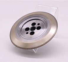
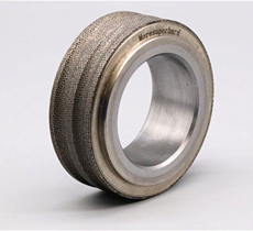
A centerless grinder is only as good as the two wheels running in it, and the specification that matters is not a catalogue number. The grinding wheel is selected against the workpiece material, the stock to remove and the required finish: coarse and open for stock removal on soft material, finer and harder for finish on hardened parts. The regulating wheel controls feed rate and part rotation, and its specification—abrasive type, hardness and surface condition—determines whether the part is driven smoothly or slips.
Dressing is where most shops lose the accuracy they paid for. Both wheels must be dressed true and concentric to their own spindles, with a controlled infeed and a consistent traverse; a regulating wheel dressed with the wrong feed produces a part with taper that looks like a machine alignment fault. Keeping the dressing log—interval, depth, and the resulting part measurement—turns roundness and taper from something the operator chases into something the process holds.


Pre-Acceptance, Installation, and Service


Machine purchases of this class are decided on acceptance terms as much as specifications. Under the standard process, the buyer supplies confirmed workpiece drawings, samples and test requirements; the seller gives at least 10 days notice of the proposed pre-acceptance date and prepares the machine; the buyer provides 10 workpieces; and pre-acceptance covers appearance, structural rigidity, no-load and full-load running records, key performance measurements, and a continuous run of 10 workpieces to drawing. Shipment follows successful pre-acceptance and signed documents. On site, the seller installs and commissions, runs grinding trials where applicable, and final acceptance is reached when parts meet the drawing.
Warranty runs one year from final acceptance, with free repair including labour and parts for covered failures under normal operation, and paid service afterwards. Operator training is included and covers setup, wheel replacement, hydraulic circuit maintenance, seals and bushings, electrical maintenance, safety, operation and basic troubleshooting, typically over one to three working days. Fault complaints receive a response and proposed solution within 12 hours, with on-site attendance within 48 hours where required.


We Build the Machine and Specify the Wheel


MoreSuperHard supplies the MSH-12S and the grinding wheels that run on it. Because the wheel specification is selected from the customer's workpiece drawings rather than from a stock list, the machine, the wheel and the process parameters arrive aligned. If you are grinding small precision shafts in the 0.5–40 mm range, send us your part drawing, material, tolerance, required Ra and target cycle time—we will quote the machine configuration and the wheel together, with acceptance criteria agreed before the order.


Frequently Asked Questions


Q: What diameter range does the MSH-12S cover?
A: 0.5 to 40 mm. It is designed for through-feed centerless grinding of small precision cylindrical parts such as pins, shafts, needles and bushings.

Q: What accuracy can the MSH-12S achieve?

A: The stated reference accuracy for a standard test workpiece is roundness ≤0.002 mm and surface roughness ≤Ra 0.2 µm. Actual results depend on workpiece material, wheel specification, dressing and parameters.

Q: How is the regulating wheel driven?

A: By a servo motor with numerical speed control from 0 to 320 rpm, driving the spindle through a synchronous belt so the motor and wheel tilt together with parallel pulleys.

Q: Why does the base material and aging matter?

A: A Meehanite FC30 cast base that is stress-relieved and aged for over six months will not move after machining. Residual stress in the base shows up as taper and roundness error that parameter tuning cannot correct.

Q: What is the typical stock removal per pass?

A: Rough grinding 0.03–0.06 mm and finish grinding 0.005–0.02 mm, with the wheel specification chosen for the workpiece material and the required finish.

Q: What warranty and service are included?

A: One year from final acceptance, with free repair including labour and parts for covered failures under normal operation; paid service after that. Fault response within 12 hours and on-site attendance within 48 hours where required.
 
FOLLOW US
This Blog keeps our valued customers informed of important Radiac News and Events, and in the industries we serve.
Copyright © 2003-2023 More SuperHard Products Co., Ltd
Home
Whatsapp
E-mail
Inquiry