NEWS
10
Oct

MPO Connector Precision Polishing: The 4-Step Process for 1800 nm Fiber Height

Share:

Why MPO Polishing Is a Different Challenge Than Single-Fiber Polishing


The MPO (Multi-fiber Push On) connector terminates 12, 24, or even higher-density fiber counts in a single ceramic ferrule. It is the backbone of modern data centers, high-speed networks at 40G/100G/400G/800G, and FTTH backbone links. Unlike single-fiber LC or SC connectors, an MPO end face packs many fibers into one ferrule—so end-face geometry, fiber-height consistency across every channel, and surface finish must all be controlled to tolerances far tighter than single-fiber assemblies. The critical process that makes this possible is precision polishing.


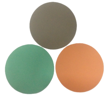
                                             MPO Grinding pad


Two Polishing Abrasives: AO1 Aluminum Oxide and CO1 Cerium Oxide


Modern MPO polishing consumables use nylon-fleece polishing cloths backed by two abrasive types, each with a specific role. Both use pure water as the only medium—no chemical slurry, easy to clean, and unrestricted for transport. The nylon fleece is soft enough to prevent scratches while the abrasive particles deliver controlled material removal.

Model Abrasive Grain Size Color Core Role
AO1 Aluminum oxide (Al2O3) 1 µm Green Rough polishing; improves flatness
CO1 Cerium oxide (CeO2) 1 µm Orange Precision polishing; ultra-low roughness


When the full process is tuned correctly, fiber height stabilizes between 1800 and 2000 nm, the first-pass yield is extremely high, and the end face is fine, defect-free, and ready for interconnection testing.


Two Proven Process Recipes: Mass-Production vs. 800G/1.6T High-End


Recipe A: Four-step mass-production process (fine grinding + fiber drawing combined).
This recipe merges fine grinding and fiber drawing into one step to maximize throughput. It is designed for high-volume MPO assembly lines where stable first-pass yield and cycle time matter most.
Step Consumable Medium Goal
Step 1: Rough grind SC16 lapping film Pure water Remove end-face defects; establish reference plane
Step 2: Fine grind / fiber draw SC3 fiber-drawing film Pure water Quick shaping; fiber height moves toward target band
Step 3: Rough polish AO1 polishing fleece (green) Pure water Rough polishing; control flatness and roughness
Step 4: Fine polish CO1 polishing fleece (orange) Pure water Remove micro-scratches; ultra-low-roughness end face

Advantages of Recipe A:
  • Fine grinding and fiber drawing combined—fewer steps, faster cycle time.
  • Pure water throughout; single-use consumables mean zero cross-contamination.
  • Compatible with pneumatic-pressure and PLC-controlled polishers; supports in-line automation.
Recipe B: Pure-lapping-film process (each step independently controlled).
This recipe separates grinding and polishing strictly, optimizing every step’s parameters independently. It targets the ultimate end-face quality required by 800G and 1.6T optical modules, where even minor defects or height variance cannot be tolerated.

Step Consumable Medium Goal
Step 1: Rough grind SC16 lapping film Pure water Remove fiber-end protrusions and cracked layers
Step 2: Fine grind SC3 repair lapping film Pure water Repair end-face defects left after etching/ferrule prep
Step 3: Fiber draw SC3 fiber-drawing film Pure water Raise fiber height to 1600–3000 nm window
Step 4: Fine polish CO1 fine-polishing film Pure water Ultrafine polishing; final end-face repair


Advantages of Recipe B:
  • Grinding and polishing strictly separated—each step’s pressure, time, and speed optimized independently.
  • Fiber height is easier to control within a tighter band (1600–3000 nm).
  • Same compatibility with pneumatic/PLC-controlled polishing machines; supports automated production cells.


Critical Process Rules: Water Is Not Optional

 
  • Always wet the polishing fleece with pure water before use. A dry fleece causes scratches and polishing pitting—this rule holds for both metallographic polishing and fiber-optic polishing.
  • Maintain continuous pure-water supply. The polymer binder in the fleece is designed to work wet: the water film acts both as lubricant and as a debris-removal channel.
  • Use single-use consumables—do not reuse lapping films or fleeces. Cross-contamination is one of the most common causes of end-face defects in high-volume MPO lines.
  • Tune pressure and time to the specific polisher. Pneumatic-pressure machines and PLC-controlled machines respond differently; the process must be qualified on the actual equipment.


Common MPO End-Face Defects—and How the Right Process Prevents Them


MPO manufacturing engineers recognize a short list of recurring defects that fail inspection and cause field returns. Each one has a root cause that the polishing process can control:
  • Scratches and digs: usually caused by a dry fleece, reused consumables, or contaminated pure water. AO1 then CO1 with continuous water supply eliminates the vast majority.
  • Fiber-height inconsistency across the array: happens when the SC3 fiber-drawing step is too short, or pressure is uneven across the 12/24-fiber ferrule. A qualified process holds every channel within the 1800–2000 nm window.
  • Chip and crack at the fiber edge: comes from aggressive rough grinding or a damaged ferrule face. SC16 rough grinding removes the cracked layer gently, and the independent-step recipe for 800G/1.6T adds a dedicated SC3 repair step.
  • Excessive curvature or roller-ball effect: caused by polishing-pad compression and machine condition. The right fleece hardness, pressure, and time keep the ferrule radius within Telcordia and IEC limits.
  • Orange peel or pitting on the zirconia ferrule: often a sign that polishing time was too long or the abrasive was loaded. Single-use consumables and process-disciplined timing prevent this.
The pattern is clear: most MPO end-face failures are not random—they are process failures. A four-step recipe with SC16/SC3 films, AO1 and CO1 fleeces, continuous pure water, and single-use consumables addresses all of them at once.


Equipment and Setup: Pneumatic vs. PLC-Controlled Polishers


Both process recipes are compatible with standard MPO polishing machines—pneumatic-pressure and PLC-controlled automatic polishers. Pneumatic machines are common in smaller assembly lines and offer good flexibility across ferrule types; PLC-controlled machines deliver repeatable pressure, time, and rotation for high-volume production. The consumables themselves are designed to run on either: the SC16 and SC3 lapping films attach to the polishing platen by pressure-sensitive backing, and the AO1 and CO1 fleece cloths are laid flat and held by vacuum or adhesive. For automated cells, the single-use nature of the films and fleeces means no manual reconditioning between cycles—simply swap the film after each batch and move on.


Why MPO Polishing Quality Matters for 800G and Beyond


As data-center speeds move from 400G to 800G and 1.6T, link budgets shrink and every dB of insertion loss and every connector return loss counts. A poorly polished MPO ferrule—scratched, chipped, or with uneven fiber height—creates loss, back-reflection, and unstable link performance across 12 or 24 channels at once. The right polishing consumables and a qualified four-step process are no longer a finishing detail; they are the primary determinant of first-pass yield and field reliability. Manufacturers that invest in stable AO1/CO1 fleece polishing and pure-water process discipline see dramatic reductions in rework, ESC (external contamination) failures, and field returns.


Why Choose Our MPO Polishing Consumables


We supply the full MPO/MTP polishing consumable set—SC16 and SC3 lapping films, AO1 aluminum-oxide polishing fleece, and CO1 cerium-oxide polishing fleece—engineered for nylon-fleece backing, pure-water-only processing, and compatibility with standard pneumatic and PLC-controlled polishers. We support both the high-volume combined-step recipe and the 800G/1.6T independent-step recipe, with application engineering to qualify your specific polisher, fiber height target, and module generation. Contact us with your connector type (MPO/APC/UPC), fiber count, and current yield—we will help you hit 1800–2000 nm fiber height with a high first-pass rate.


Frequently Asked Questions


Q: What is MPO polishing?
A: MPO polishing is the precision end-face finishing process applied to Multi-fiber Push On connectors, which terminate 12, 24, or higher fiber counts in one ceramic ferrule. It controls end-face geometry, fiber-height consistency, and surface finish for data-center and high-speed optical links.

Q: What is the difference between AO1 and CO1 polishing fleece?

A: AO1 uses 1 µm aluminum oxide and is green—used for rough polishing to improve flatness. CO1 uses 1 µm cerium oxide and is orange—used for fine polishing to achieve ultra-low roughness and remove micro-scratches. Both use pure water as the only medium.

Q: What fiber height should MPO polishing target?

A: A well-tuned MPO process stabilizes fiber height between 1800 and 2000 nm. For high-end 800G/1.6T recipes using independent lapping-film steps, the controlled window is typically 1600–3000 nm.

Q: Can I reuse MPO polishing films or fleeces?

A: No. Single-use consumables are a core process rule—reusing lapping films or fleeces causes cross-contamination, scratches, and end-face defects. Pure-water-only processing makes cleanup easy and transport unrestricted.

Q: Why must polishing fleece be wet with pure water?

A: A dry fleece causes scratches and pitting. The polymer binder is designed to work wet: the water film lubricates and flushes away debris. Continuous pure-water supply is required throughout the polishing step.

Q: Which process recipe is right for 800G/1.6T modules?

A: For 800G/1.6T high-end modules, use the independent-step pure-lapping-film recipe: SC16 rough → SC3 repair → SC3 fiber draw → CO1 fine polish. This separates grinding and polishing so each step is independently optimized for the tightest end-face quality.
 
FOLLOW US
This Blog keeps our valued customers informed of important Radiac News and Events, and in the industries we serve.
Copyright © 2003-2023 More SuperHard Products Co., Ltd
Home
Whatsapp
E-mail
Inquiry