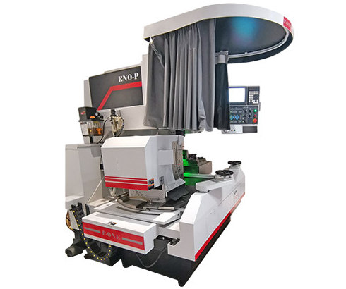
Welcome to the installation guide for the
Optical Grinding Machine. This guide is designed by More Super Hard to provide comprehensive instructions for installing and setting up your optical grinding machine efficiently and safely. Proper installation is crucial to ensure optimal performance and longevity of your equipment. Before proceeding with the installation process, please carefully review the instructions outlined in this guide and ensure you have all the necessary tools and equipment readily available. Let’s embark on this installation journey to unleash the full potential of your optical grinding machine.
Content
1. Main parts of the
Optical Grinding Machine
1.1 Names and functions of the main parts of Optical Grinding Machine
2. Grinding wheel table
2.1 Relationship between grinding wheel table and projection range
2.2 Setting angle adjustment
3. Grinding wheel lifting function
3.1 Change of lift travel length
3.1.1 Adjustment of lift travel length
3.1.2 Lifting table position adjustment
3.2 Lift travel position
3.3 Lift-and-turn operation
3.3.1 Lifting table forward and reverse adjustment knob
3.4 Control methods of lift-and-turn speed
3.4.1 Action
4. Worktable
4.1 Worktable up and down movement
4.2 Relationship between worktable up and down movement and the focus
4.3 The movement range of worktable to optical axis center
5. Oil cooler
5.1 Oil cooler installation
5.2 Operation methods
6. Pneumatic unit
6.1 Pneumatic unit
6.2 Air dryer
6.3 Air quality grade
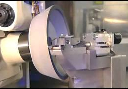
7. Grinding wheel and flange
6.4 Preparation and confirmation
6.5 Balance adjustment of grinding wheel
6.6 Installation and removal of grinding axle
1. Main parts of the
Optical Grinding Machine
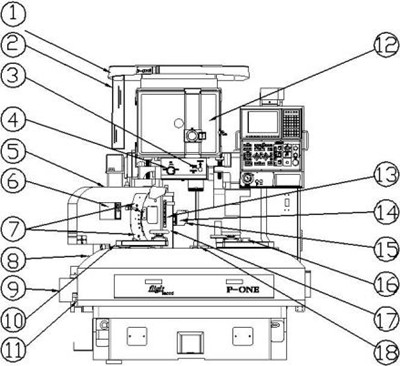
| 1 |
Light shield |
11 |
Top rotating table of
grinding wheel table |
| 2 |
Shading curtain |
12 |
Screen |
| 3 |
Reflected illumination switching
handle |
13 |
Grinding wheel lifting process amount adjustment device |
| 4 |
Magnification switching
handle |
14 |
Grinding wheel shield |
| 5 |
Front setting angle adjusting
device |
15 |
Grinding wheel vehicle |
| 6 |
The rocker for adjusting the lifting position of grinding wheel |
16 |
Auxiliary worktable |
| 7 |
Front setting angle solid rocker |
17 |
Grinding wheel lifting table |
| 8 |
Rotating handle |
18 |
Transmissive illumination device |
| 9 |
Y-axis AC servo motor |
|
|
| 10 |
Side setting angle adjustment device |
|
|
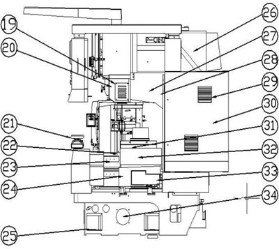
| 19 |
Reflected illumination device cooling fan |
28 |
Main power switch |
| 20 |
Reflecting device |
29 |
Control cabinet cooling fan |
| 21 |
Grinding wheel table transverse feed handle (Y axis) |
30 |
Control cabinet |
| 22 |
Worktable longitudinal feed table (Z axis) |
31 |
Worktable up and down movement device |
| 23 |
Worktable transverse feed table (V axis) |
32 |
Worktable up and down movement motor |
| 24 |
V-axis AC servo motor |
33 |
Z-axis AC servo motor (in the
shield) |
| 25 |
Jacking screw |
34 |
Transmissive illumination cooling fan
P-ONE |
| 26 |
Projector |
| 27 |
Suspension wall |
|
|
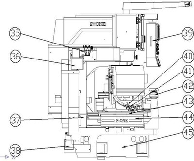
| 35 |
Pneumatic unit |
41 |
Rotating table securing rocker |
| 36 |
Automatic lubrication pump |
42 |
Worktable longitudinal feed handle |
| 37 |
X-axis AC servo motor |
43 |
Grinding wheel table longitudinal
feed table (X axis) |
| 38 |
Plastic oil tank for waste oil
recovery |
44 |
Grinding wheel table transverse feed table (Y-axis) |
| 39 |
Operating cabinet |
45 |
Grinder body |
| 40 |
Side setting angle securing rocker |
|
|
2. Grinding wheel table of
Optical Grinding Machine
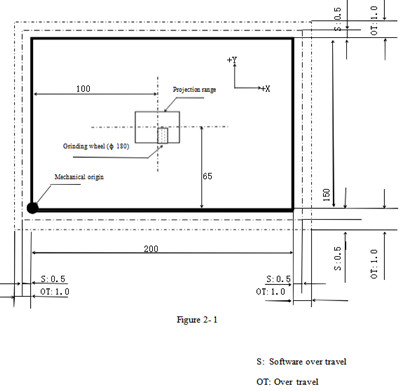
2.1 Relationship between grinding wheel table and projection range
The screen center position and mechanical origin, X and Y axis travel ranges are shown in the following figure (Figure 2- 1)
2.2 Setting angle arrangement
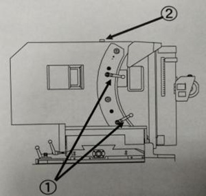
2.2.1Adjustment of front setting angle
( 1) Release the lock rocker ①
(2) Rotate the shaft ② with ratchet handle. It can be tilted from -2° to 20° .
(3) Adjust the forward setting angle and tighten the lock rocker ①
2.2.2 Adjustment of side setting angle
( 1) Loosen the lock rocker ③
(2) Rotate the shaft ⑥ with ratchet handle and extended sleeve. It can be tilted at ± 15° .
(3) Adjust the side setting angle and tighten the lock rocker ③.
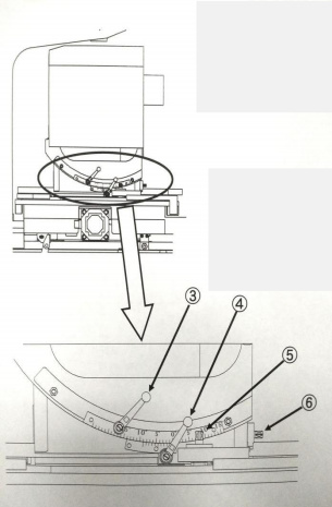
2.2.3 Adjustment of rotation angle
( 1) Release the lock rocker ④.
(2) Rotate the shaft ⑤ with ratchet handle. It can be tilted at ±15° .
(3) Tighten the lock rocker ④
3. Grinding wheel lifting function
3.1 Change of lift travel length
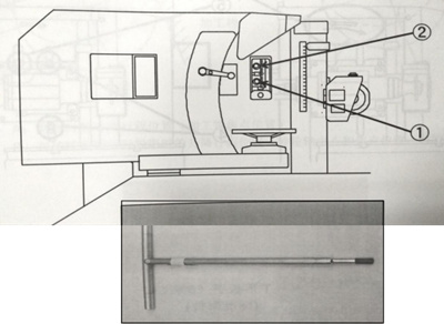
3.1.1 Adjustment of lift travel length Adjust the lift travel as follows.
(1) Put down the shutter and release the lifting clamp ①.
(2) Adjust the lift travel by turning the adjustment nuts by using the attached T-wrench (8) and referring to the lifting stroke ②.
(3)After adjusting the lift travel, tighten the lifting clamp ① again and close the shutter.
3.1.2 Lifting table position adjustment
Adjust the position of the lifting table according to the following steps.
1. Open the shutter ③.
2. Open the shutter so that the clamp nuts (2 places) and the lifting position adjustment nuts can be seen. Use the attached T-handled wrench (6) to loosen the clamp nut ④ (2 places).
3. Use the attached T-handled wrench (6) in the standard accessory to adjust the position by lifting the position adjustment nut ⑤.
4. After the position adjustment is completed, re-tighten the clamp nut ④ (2 places).
5. Close the shutter.
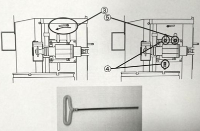
Attention: After adjusting the lifting position, please manually confirm the upper and lower dead points before machining.
3.2 Lift travel position
After the front setting angle is changed, the projection position of the grinding wheel will change during grinding. Please refer to the following figure of lift travel position (P3-4) to set the travel position.
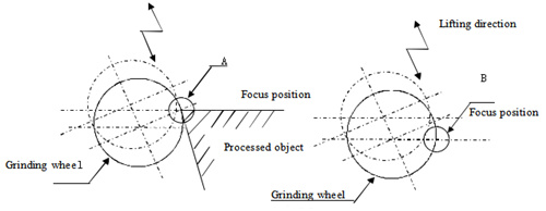
A: lifting stroke position during grinding (focus position of processed object)
B: The lift travel position when projecting the front end of the grinding wheel (the position where the center of the grinding wheel spindle coincides with the focus position)
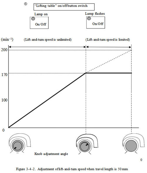
3.3 Lift-and-turn operation
Adjust the lift-and-turn speed at the position shown on the operation cabinet in Figure 3-3- 1. Press the “Lift on/off” button to turn on the button lamp and start the lifting table.
Press the button again to stop the lifting table. Rotate the knob counterclockwise, the speed of the lifting table slows down.
Turn the knob counterclockwise to the end, the lifting table stops, but the “lifting table
on/off” button lamp remains on and the lifting command is not released. If you want to stop the lifting table, press the “lifting table on/off” button again to turn off the lamp.
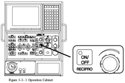
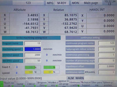
Display of lift-and-turn speed
The speed of the lifting table is indicated on the screen (the fastest speed matches the system input speed). (Refer to Figure 3-2-2)
3.3.1 Lift table forward and reverse rotation adjustment knob
Turn counterclockwise for reverse rotation. Turn clockwise for forward rotation.
3.4 Control methods of lift-and-turn speed
The lifting table is balanced by the pneumatic cylinder, and the maximum lift-and-turn speed is 400min-1. However, due to the structure of the lifting table, the lift-and-turn speed is limited according to the travel of the lifting table. As shown in Fig. 3-4- 1, the upper limit of the lift-and-turn speed is within the range of 90 to 400min-1according to the lift travel.
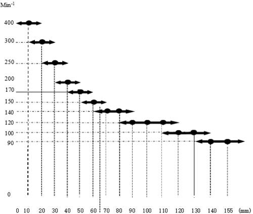
Note: The unit of the lift travel is 10mm. Therefore, the reading error of the reverse control
is 10mm. When the travel volume is not an integer multiple of 10, the travel volume is limited according to the previous or subsequent travel. For example, if the lift travel is 65mm, the reading is 60mm or 70mm. Therefore, the speed limit is 140min-1 or 150min-1.
3.4.1 Action
For example, when the lift travel is 50mm, the maximum speed can be adjusted to 170min-1 by using the lift-and-turn speed adjustment knob. When the speed reaches 170 min-1, the speed cannot be increased even if the lift-and-turn speed knob is turned clockwise to the end. When the lift-and-turn speed knob is turned counterclockwise to reduce the speed below 170min-1, the lift-and-turn speed adjustment knob can be used again for adjustment. The same is true for other lift travel. (Refer to Figure 3-4-2)
4. Workbench
4.1 Worktable up and down movement
Press the button on the operation panel to move the worktable up and down. Execute the pulse control of up and down movement speed by servo motor.
4.2 The relationship between the up and down movement of the worktable and the focus
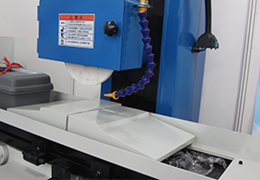
5. Oil cooler
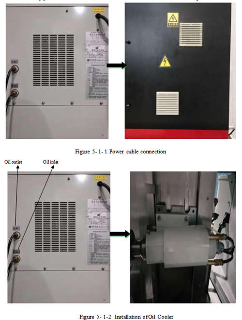
5.1 Oil cooler installation
Connect the pipes between the machine and the oil cooler, as shown in the figure.
5.2 Operation methods
1 The oil cooler on the hydraulic unit can only be turned on after the NC power of the machine is turned on.
2 The temperature can be set on the setting panel in front of the oil cooler.
It can set “actual temperature” and “set temperature” on the panel, and the unit for setting temperature is 0. 1 ℃.
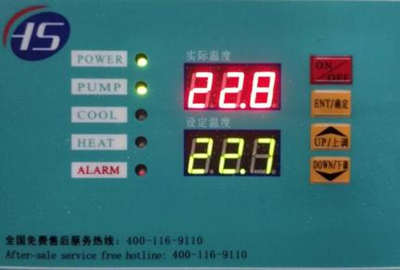
Note: The oil cooler has been set the “fixed temperature” before delivery.
When setting the temperature, please set the temperature 1 ℃ below the room temperature. (If the room temperature is 20 ℃, the setting temperature should be 19 ℃)
The inappropriate oil temperature setting may cause poor accuracy, so please do not make change the temperature without special needs.
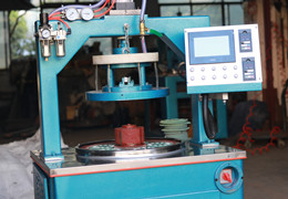
6. Pneumatic unit
6.1 Pneumatic unit
Air supply is necessary for the air purging of the lifting table cylinder and spindle. Please supply air source with pressure above 0.5Mpa at the installation site.
The main line filter, mist separator and compressed air purifier can discharge waste water automatically.
If the compressed air contains large amount of moisture, dust and oil, the main line filter and the mist separator will be unable to remove these impurities, and the life of the filter element of the main line filter and the mist separator will be greatly shortened.
When impurities enter the machine, it will shorten the life of the lifting cylinder, spindle, etc., so be sure to replace the filter element and clean the inside of the filter.
Note: Check the filter elements of the main line filter and the mist separator once a month. If the oil color changes, please replace the filter element as soon as possible. If the oil color does not change but the pressure drops (the pointer of the blockage confirmation device turns red), please also replace the filter
elements.
Replacement of the filter element
As there is no filter in the compressed air purifier, no replacement is required.
6.2 Air dryer
Install an air dryer to remove vapor from the factory air supply and use the electric vacuum cleaner or blower to clean the dust at the air vent. As the vent may emit heat, do not cover or block the vent. Refer to the operating instructions of the air dryer (4- 1) for details.
Install the main line filter in the air dryer to remove the oil, dust, moisture, etc. contained in the factory air supply and protect the air dryer. The accumulation of dust will cause pressure dropdown. Please implement the same procedure for filter element inspection and replacement in the 6. 1.
Note: Check the filter elements of the main line filter once a month. If the oil color changes, please replace the filter element as soon as possible. If the oil color does not change but the pressure drops (the pointer of the blockage confirmation device turns red), please also replace the filter elements.
Replacement of the filter element
6.3 Air quality grade
Please supply air with quality grade (3,6,-) or above to this machine through refrigeration dryer, main line filter, etc. The quality grade of the air after passing the compressed air purifier, main line filter, the mist separator is ( 1,6,2). In order to protect the spindle and ensure the air supply quality, please conduct maintenance.
Grade |
Solid particle |
| The maximum quantity of materials per 1m3 |
Particle size |
Concentration |
Particle size
dμm |
| ≤0. 10 |
0. 10<d≤0.5 |
0.5<d≤1.0 |
1.0<d≤5.0 |
N/A |
N/A |
| 1 |
Not
specified |
|
|
|
| 2 |
Not
specified |
|
|
|
| 3 |
Not
specified |
|
|
|
| 4 |
Not
specified |
|
|
|
| 5 |
Not
specified |
|
|
|
| 6 |
N/A |
≤5 |
≤5 |
| 7 |
N/A |
≤40 |
≤10 |
7. Grinding wheel and flange
7.1 Preparation and confirmation
Before installing the grinding wheel on the grinder, please check the appearance of the grinding wheel. Check the grinding wheel with an outer diameter of over 100mm. Please tap the grinding wheel lightly with a mallet and listen to the sound. If the sound is clear, there is no problem. If the sound is difficult to distinguish, check two more grinding wheels. If the sound from the grinding wheel is the same as other grinding wheels, there is no problem. It should be noted that, in such case, the grinding wheels with the same adhesive must be used. If the sound from the grinding wheel is muddy, the grinding wheel may be damaged during transportation, storage or handling. Do not use it. For grinding wheels with an outer diameter of less than ¢ 100mm, the sound check is invalid. Please visually check the appearance carefully.
When tightening the grinding wheel on the flange, if there is no label on the grinding wheel, please put a piece of wet paper (such as blotting paper) with thickness of 0.4mm~0.5mm between the grinding wheel and the flange from both sides. If one sheet of wet paper is not enough, please use more pieces of paper. After installing the grinding wheel, please confirm the fastening conditions of the grinding wheel and flange, and flange and grinding wheel spindle.
Attention: During preparation, please ensure the safety of the grinding wheel as described above.
7.2 Balance adjustment of grinding wheel
Before grinding operation, please adjust the balance of grinding wheel. If grinding wheel starts running without adjusting the balance, it will swing back and forth, causing mechanical vibration and resulting in vibration on the grinding surface or adverse effects on grinder functions. However, for grinding wheels with a thickness of less than 6mm or an outer diameter of less than 150mm, no balance adjustment is required for safety. The balance of the grinding wheel can be corrected by adjusting the position of the balance sheet on the flange of the grinding wheel, or using a semi- automatic balancer and follow the instructions.
Note: Even if the balance has been fully adjusted, the balance error may occur as the outer diameter of the grinding wheel becomes smaller due to changes in the internal structure of the grinding wheel.
Therefore, it needs to be readjusted in time.
7.3 Installation and removal of grinding wheel
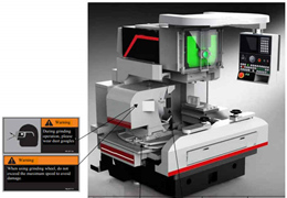
.jpg)
Warning:When you install the grinding wheel on the grinding wheel spindle, remember to install the grinding wheel protective cover. If the grinding wheel is damaged during rotating, the fragments will fly out and may cause severe injury.