Coordinate Grinding Precision Hole Grinding
CNC coordinate grinder is used to process continuous dies of electronic components, fine punching dies, scoring dies and engineering plastic dies of camera and watch parts.
How many types of coordinate grinding are there? (Coordinate grinder)
The worktable processed by the coordinate grinder is composed of a coordinate worktable and a reverse worktable. The coordinate workbench is a set of guide rail systems of high-precision rectangular coordinate system. The coordinate work table is located on the reverse work table, and the arc base for adjusting the workpiece coincides with the base of the reverse work table. During grinding, the workpiece is placed on the workbench, and the z and y coordinates can be moved and reversed, so as to carry out the forming summary and the processing of the hole.
Using a coordinate grinder, it can grind inner holes, outer circles, tapered holes, coordinate holes, stepped holes, stepped surfaces, keyways, square holes, and curves composed of straight lines and arcs. Like coordinate boring, the workpiece must be positioned and aligned before grinding. After alignment, use the vertical and horizontal movement of the worktable to make the machine tool spindle base coincide with the workpiece arc base, and then grind.
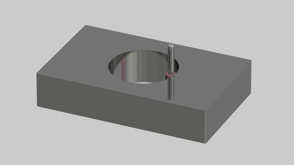
(4) Coordinate hole grinding
Using a coordinate grinder to grind coordinate holes is a commonly used processing method, and the coordinate grinder is also named after it. In addition, it is also possible to grind polar coordinates. When grinding the coordinate holes, the movement of the coordinate table can be used to process coordinate holes of various sizes, and the azimuth accuracy can reach 2 to 5 m. Therefore, the coordinate grinding machine is particularly suitable for the dressing processing of the coordinate hole deformed by quenching after machining with the coordinate boring machine. When grinding polar coordinate holes, there are two methods:
One is the indexing method, which uses the reverse worktable for indexing;
Coordinate grinder
The second is the coordinate method, which uses rectangular coordinates for calculation.
When the polar coordinate radius of the part is small and there are many indexing holes, the indexing method is used for high machining accuracy, economical and convenient; and when the polar coordinate radius is large, due to the influence of the rotation accuracy, the coordinate method can be used to obtain higher machining accuracy. precision. In addition, on the coordinate grinding machine, the space plane, space polar coordinate hole and various inclined holes on the part can also be ground by using the tiltable work table and through the coordinate meter.
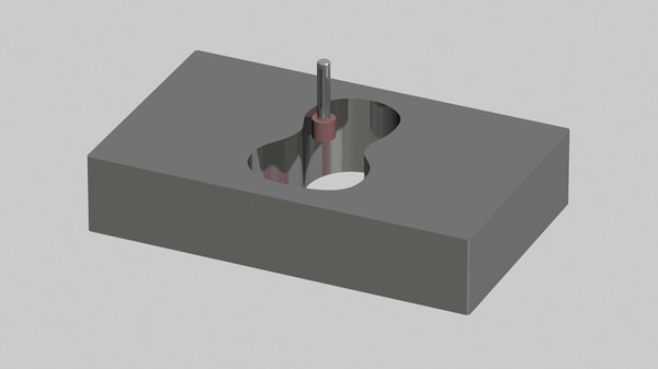
(5) Step hole grinding
When grinding stepped holes, the radius of planetary motion should be determined according to the diameter of the hole to be ground, and the grinding wheel should be fed downward, and the bottom edge should be used for grinding.
Grind the bottom end face of the grinding wheel to 3. Orbital concave surface to improve grinding power and facilitate chip evacuation. When grinding, adjust the planetary movement to the required outer diameter or shape, and the grinding wheel performs axial feed motion to grind with the end face and sharp corner of the grinding wheel. When grinding the shoulder hole of the table, the diameter of the grinding wheel is about the sum of the radius of the large hole and the radius of the through hole; when grinding the blind hole, the diameter of the grinding wheel is about half of the hole diameter. Precision grinding machine processing
(6) Step linear grinding
The grinding wheel only performs rotary motion without planetary motion, and the workpiece moves in a straight line, which is suitable for precision grinding on a flat surface.
(7) Keyway and square hole grinding
Using special grinding groove structure and grinding wheel, it can grind keyway, cavity with right angle and square hole, etc. It is also suitable for grinding groove and inner and outer cavity with clear angle. The grinding groove structure is driven by the grinding wheel shaft, and its principle is similar to the principle of the main movement during planing. During grinding, in addition to rotating motion, the grinding wheel also performs up and down reciprocating linear motion, and the workpiece moves linearly.
(8) Curved grinding
When grinding a curve formed by a straight line and a circular arc, the accurate azimuth dimension between the straight line and the circular arc is ensured by the positioning accuracy of the coordinate table movement. After positioning, use the fixed-point machining method to grind the arc. The so-called fixed-point machining method is to use the movement of double y coordinates to make the base of the reverse worktable coincide with the base of the arc on the workpiece, and to control the radius of the arc by changing the radius of the planetary motion.
By summarizing and applying the above-mentioned basic grinding methods, various shapes and shapes can be processed. For example: Grind the concave model hole shown in Figure 6-37, install the workpiece on the coordinate work table, and adjust the machine tool to make the axis on the workpiece 0. Coinciding with the base of the turntable and the spindle base of the machine tool, the inner hole grinding method is used to grind the arc segment of 0, and then the same adjustment method is used to make the 0. It coincides with the base of the turntable and the spindle base of the machine tool, grinds out the arc segment of O:, and rotates the reversing table by 180 degrees. , you can grind out D. arc segment. Grinding 0. , D. D. , D, in the case of arc segments, the bases of each segment should be coincident with the base of the turntable and the base of the main shaft, respectively, and the cylindrical grinding method should be used to carry out segment by segment, and the convex and concave arcs of each segment should be connected smoothly.
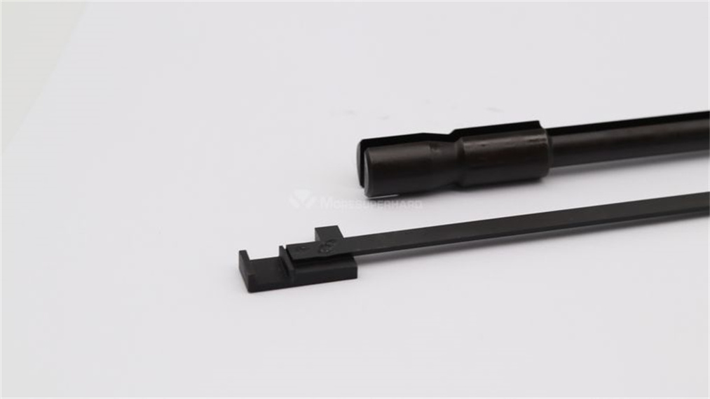
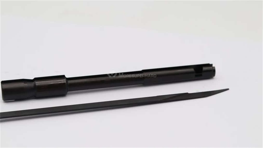
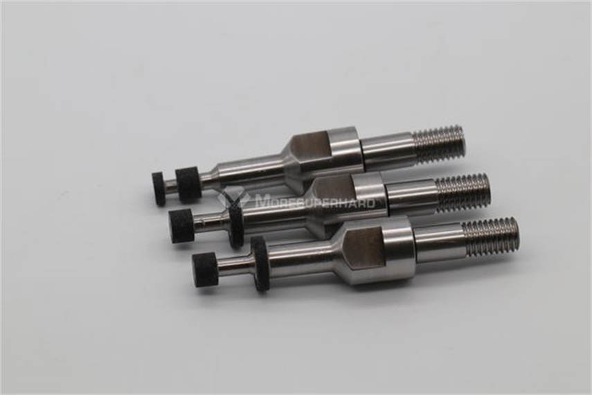
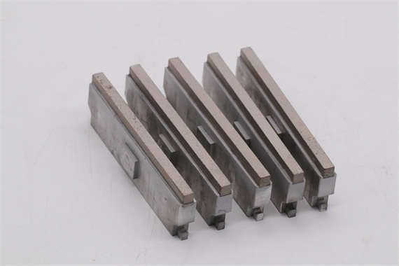
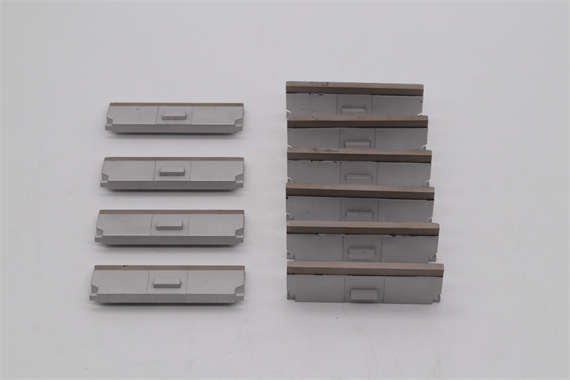
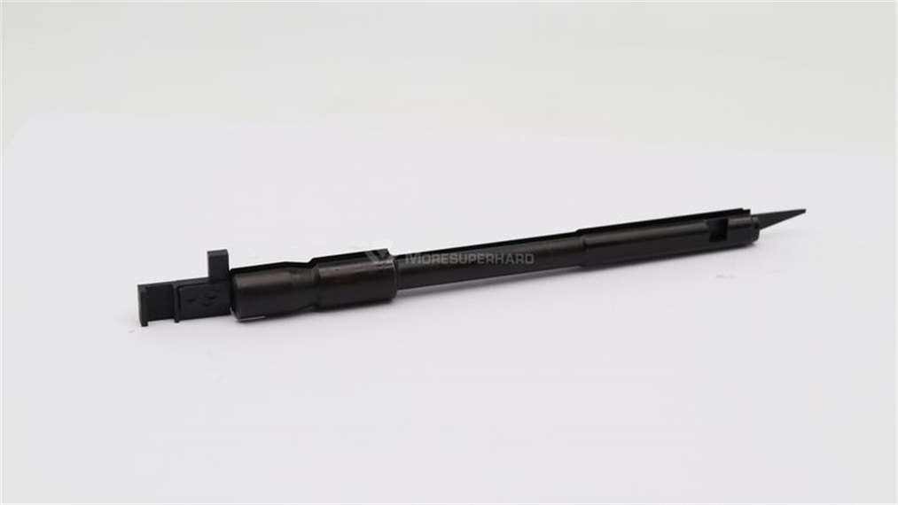
With the progress of mold manufacturing precision and automation, CNC coordinate grinders and continuous orbit CNC coordinate grinders have been developed at home and abroad. Its main feature is that it can perform high-precision general shape processing and make the gap between the convex and concave molds uniform. Using a set of procedures, parts with similar dimensions such as punch, die, and stripper plate can be processed, with good adaptability. In addition, unattended processing can be performed one after another without being affected by the operator’s proficiency. Thus, productivity and automation are high. Tungsten steel punch
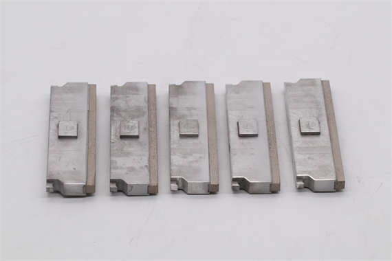
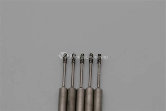
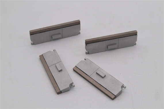
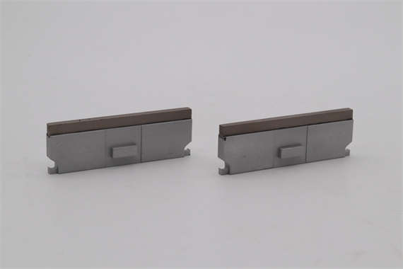
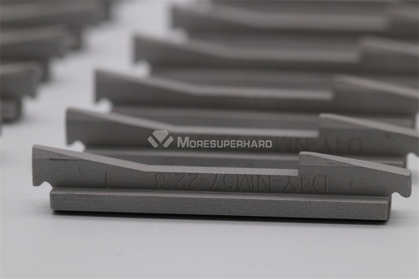
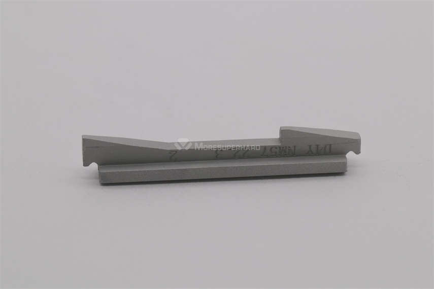
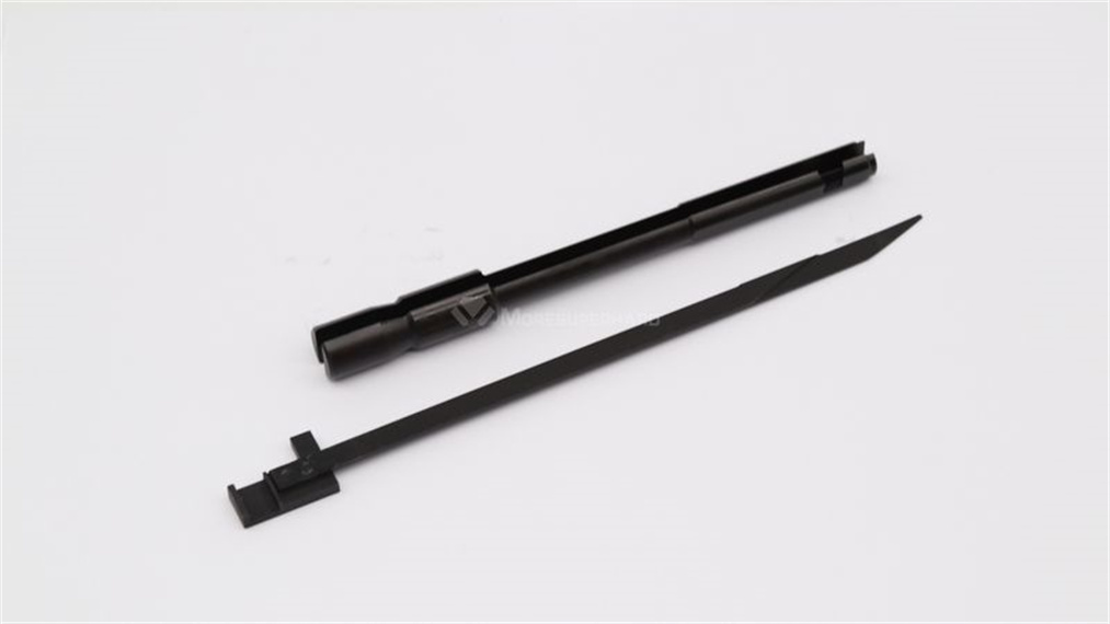
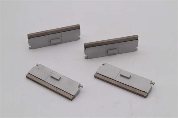
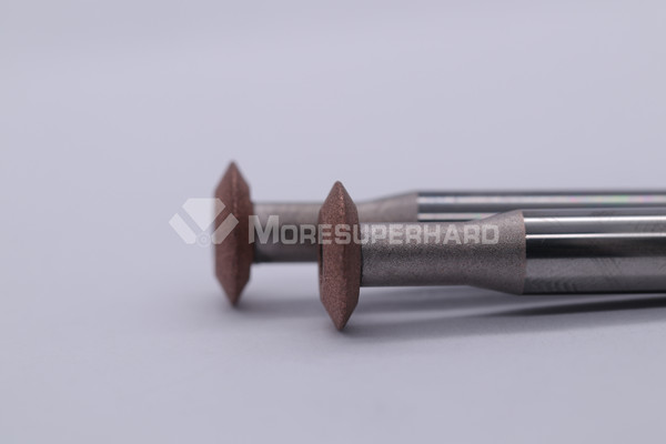
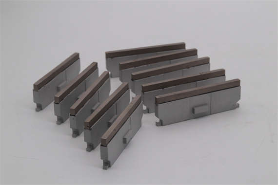
CNC coordinate grinder is used to process continuous dies of electronic components, fine punching dies, scoring dies and engineering plastic dies of camera and watch parts. For example, a scoring die for an open can is machined using a continuous orbital CNC coordinate grinder. The function of the die is to punch the opening marks on the can lid, so that when the pull ring is pulled, the pull ring will be pulled off together with some sheets in the marks, and the can lid will be opened along the marks. Its main working surface is a special-shaped surface with complex shapes. The production accuracy of the die depth and cutting edge width is required to be high, and each curve needs to be smoothly transitioned. To this end, the heat-treated notch die blank is formed by an EDM machine to form a special-shaped surface that meets the requirements. Then install it on the continuous orbital CNC coordinate grinding machine, align it with a hole with a diameter of 3.28mm, and use the programmed program to grind it with a cubic boron nitride grinding wheel. First, grind the two sides of the special-shaped surface with a forming grinding wheel, and then use a flat grinding wheel to fine-grind the edge plane until its width and height meet the design requirements.